06-MPLS L3VPN配置
本章节下载: 06-MPLS L3VPN配置 (1.73 MB)
目 录
1.7.3 配置BGP引入Loopback接口地址和OSPF的路由
1.10.1 PE-CE间使用EBGP基本MPLS L3VPN配置示例
1.10.2 PE-CE间使用IBGP基本MPLS L3VPN配置示例
2.1.4 IPv6 MPLS L3VPN支持的组网方案及功能
![]()
· 本章只涉及MPLS L3VPN的介绍和配置,有关MPLS基本配置的介绍请参见 “MPLS基本配置”,有关BGP的介绍请参见“三层技术-IP路由配置指导”中的“BGP”。
· 目前,如果需要使用MPLS L3VPN的相应功能,需要配备SD系列业务板,并使用该业务板上的端口连接用户网络和运营商网络。
MPLS L3VPN是服务提供商VPN解决方案中一种基于PE的L3VPN技术,它使用BGP在服务提供商骨干网上发布VPN路由,使用MPLS在服务提供商骨干网上转发VPN报文。
MPLS L3VPN组网方式灵活、可扩展性好,并能够方便地支持MPLS QoS和MPLS TE,因此得到越来越多的应用。
MPLS L3VPN模型由三部分组成:
· CE(Customer Edge)设备:用户网络边缘设备,有接口直接与SP(Service Provider,服务提供商)相连。CE可以是路由器或交换机,也可以是一台主机。CE“感知”不到VPN的存在,也不需要必须支持MPLS。
· PE(Provider Edge)设备:服务提供商网络边缘设备,与用户的CE直接相连。在MPLS网络中,对VPN的所有处理都发生在PE上。
· P(Provider)设备:服务提供商网络中的骨干设备,不与CE直接相连。P设备只需要具备基本MPLS转发能力。
图1-1是一个MPLS L3VPN组网方案的示意图。
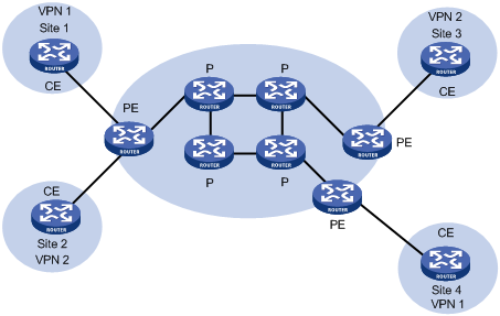
CE和PE的划分主要是根据服务提供商与用户的管理范围,CE和PE是两者管理范围的边界。
CE设备通常是一台路由器,当CE与直接相连的PE建立邻接关系后,CE把本站点的VPN路由发布给PE,并从PE学到远端VPN的路由。CE与PE之间使用BGP/IGP交换路由信息,也可以使用静态路由。
PE从CE学到CE本地的VPN路由信息后,通过BGP与其它PE交换VPN路由信息。PE路由器只维护与它直接相连的VPN的路由信息,不维护服务提供商网络中的所有VPN路由。
P路由器只维护到PE的路由,不需要了解任何VPN路由信息。
当在MPLS骨干网上传输VPN流量时,入口PE做为Ingress LSR(Label Switching Router,标签交换路由器),出口PE做为Egress LSR,P路由器则做为Transit LSR。
在介绍VPN时经常会提到“Site”,Site(站点)的含义可以从下述几个方面理解:
· Site是指相互之间具备IP连通性的一组IP系统,并且,这组IP系统的IP连通性不需通过服务提供商网络实现;
· Site的划分是根据设备的拓扑关系,而不是地理位置,尽管在大多数情况下一个Site中的设备地理位置相邻;
· 一个Site中的设备可以属于多个VPN,换言之,一个Site可以属于多个VPN;
· Site通过CE连接到服务提供商网络,一个Site可以包含多个CE,但一个CE只属于一个Site。
对于多个连接到同一服务提供商网络的Sites,通过制定策略,可以将它们划分为不同的集合(set),只有属于相同集合的Sites之间才能通过服务提供商网络互访,这种集合就是VPN。
VPN是一种私有网络,不同的VPN独立管理自己使用的地址范围,也称为地址空间(Address Space)。
不同VPN的地址空间可能会在一定范围内重合,比如,VPN 1和VPN 2都使用了10.110.10.0/24网段的地址,这就发生了地址空间重叠(Overlapping Address Spaces)。
在MPLS VPN中,不同VPN之间的路由隔离通过VPN实例(VPN-instance)实现。
PE为直接相连的Site建立并维护VPN实例。VPN实例中包含对应Site的VPN成员关系和路由规则。如果一个Site中的用户同时属于多个VPN,则该Site的VPN实例中将包括所有这些VPN的信息。
为保证VPN数据的独立性和安全性,PE上每个VPN实例都有相对独立的路由表和LFIB(Label Forwarding Information Base,标签转发表)。
具体来说,VPN实例中的信息包括:标签转发表、IP路由表、与VPN实例绑定的接口以及VPN实例的管理信息。VPN实例的管理信息包括RD(Route Distinguisher,路由标识符)、路由过滤策略、成员接口列表等。
传统BGP无法正确处理地址空间重叠的VPN的路由。假设VPN 1和VPN 2都使用了10.110.10.0/24网段的地址,并各自发布了一条去往此网段的路由,BGP将只会选择其中一条路由,从而导致去往另一个VPN的路由丢失。
PE路由器之间使用MP-BGP来发布VPN路由,并使用VPN-IPv4地址族来解决上述问题。
VPN-IPv4地址共有12个字节,包括8字节的RD和4字节的IPv4地址前缀,如图1-2所示。
图1-2 VPN-IPv4地址结构

PE从CE接收到普通IPv4路由后,需要将这些私网VPN路由发布给对端PE。私网路由的独立性是通过为这些路由附加RD实现的。
SP可以独立地分配RD,但必须保证RD的全局唯一性。这样,即使来自不同服务提供商的VPN使用了同样的IPv4地址空间,PE路由器也可以向各VPN发布不同的路由。
建议为PE上每个VPN实例配置专门的RD,以保证到达同一CE的路由都使用相同的RD。RD为0的VPN-IPv4地址相当于全局唯一的IPv4地址。
RD的作用是添加到一个特定的IPv4前缀,使之成为全局唯一的VPN IPv4前缀。
RD或者是与自治系统号(ASN)相关的,在这种情况下,RD是由一个自治系统号和一个任意的数组成;或者是与IP地址相关的,在这种情况下,RD是由一个IP地址和一个任意的数组成。
RD有三种格式,通过2字节的Type字段区分:
· Type为0时,Administrator子字段占2字节,Assigned number子字段占4字节,格式为:16bits自治系统号:32bits用户自定义数字。例如:100:1
· Type为1时,Administrator子字段占4字节,Assigned number子字段占2字节,格式为:32bitsIPv4地址:16bits用户自定义数字。例如:172.1.1.1:1
· Type为2时,Administrator子字段占4字节,Assigned number子字段占2字节,格式为:32bits自治系统号:16bits用户自定义数字,其中的自治系统号最小值为65536。例如:65536:1
为保证RD的全局唯一性,建议不要将Administrator子字段的值设置为私有AS号或私有IP地址。
(1) VPN Target属性
MPLS L3VPN使用BGP扩展团体属性——VPN Target(也称为Route Target)来控制VPN路由信息的发布。
PE路由器上的VPN实例有两类VPN Target属性:
· Export Target属性:在本地PE将从与自己直接相连的Site学到的VPN-IPv4路由发布给其它PE之前,为这些路由设置Export Target属性;
· Import Target属性:PE在接收到其它PE路由器发布的VPN-IPv4路由时,检查其Export Target属性,只有当此属性与PE上VPN实例的Import Target属性匹配时,才把路由加入到相应的VPN路由表中。
也就是说,VPN Target属性定义了一条VPN-IPv4路由可以为哪些Site所接收,PE路由器可以接收哪些Site发送来的路由。
与RD类似,VPN Target也有三种格式:
· 16bits自治系统号:32bits用户自定义数字,例如:100:1。
· 32bits IPv4地址:16bits用户自定义数字,例如:172.1.1.1:1。
· 32bits自治系统号:16bits用户自定义数字,其中的自治系统号最小值为65536。例如:65536:1。
(2) SoO属性
SoO(Site of Origin,源站点)是BGP的一种扩展团体属性,用来标识路由的原始站点。路由器不会将带有SoO属性的路由发布给SoO指定的站点。AS路径丢失时,通过SoO属性可以防止自己发布的路由被其他邻居转发回来,避免发生环路。
SoO属性有三种格式:
· 16bits自治系统号:32bits用户自定义数字,例如:100:1。
· 32bits IPv4地址:16bits用户自定义数字,例如:172.1.1.1:1。
· 32bits自治系统号:16bits用户自定义数字,其中的自治系统号最小值为65536。例如:65536:1。
![]()
每条路由只能携带一个SoO属性。
MP-BGP(Multiprotocol Border Gateway Protocol,多协议边界网关协议)在PE路由器之间传播VPN组成信息和路由。MP-BGP向下兼容,既可以支持传统的IPv4地址族,又可以支持其他地址族(比如VPN-IPv4地址族)。使用MP-BGP既确保VPN的私网路由只在VPN内发布,又实现了MPLS VPN成员间的通信。
在通过入口、出口扩展团体来控制VPN路由发布的基础上,如果需要更精确地控制VPN路由的引入和发布,可以使用入方向或出方向路由策略。
入方向路由策略根据路由的VPN Target属性进一步过滤可引入到VPN实例的路由,它可以拒绝接收引入列表中的团体选定的路由,而出方向路由策略则可以拒绝发布输出列表中的团体选定的路由。
VPN实例创建完成后,可以选择是否需要配置入方向或出方向路由策略。
隧道策略用于选择给特定VPN实例的报文使用的隧道。
隧道策略是可选配的,VPN实例创建完成后,就可以配置隧道策略。缺省情况下,按照LSP隧道->CR-LSP隧道的优先级顺序选择隧道,负载分担条数为1,即不进行负载分担。另外,隧道策略只在同一AS域内生效。
在基本MPLS L3VPN应用中(不包括跨域的情况),VPN报文转发采用两层标签方式:
· 第一层(外层)标签在骨干网内部进行交换,指示从PE到对端PE的一条LSP。VPN报文利用这层标签,可以沿LSP到达对端PE;
· 第二层(内层)标签在从对端PE到达CE时使用,指示报文应被送到哪个Site,或者更具体一些,到达哪一个CE。这样,对端PE根据内层标签可以找到转发报文的接口。
特殊情况下,属于同一个VPN的两个Site连接到同一个PE,这种情况下只需要知道如何到达对端CE。
以图1-3为例,说明VPN报文的转发:
图1-3 VPN报文转发示意图
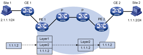
(1) Site 1发出一个目的地址为1.1.1.2的IP报文,由CE 1将报文发送至PE 1。
(2) PE 1根据报文到达的接口及目的地址查找VPN实例表项,匹配后将报文转发出去,同时打上内层和外层两个标签。
(3) MPLS网络利用报文的外层标签,将报文传送到PE 2(报文在到达PE 2前一跳时已经被剥离外层标签,仅含内层标签)。
(4) PE 2根据内层标签和目的地址查找VPN实例表项,确定报文的出接口,将报文转发至CE 2。
(5) CE 2根据正常的IP转发过程将报文传送到目的地。
在MPLS L3VPN网络中,通过VPN Target属性来控制VPN路由信息在各Site之间的发布和接收。VPN Export Target和Import Target的设置相互独立,并且都可以设置多个值,能够实现灵活的VPN访问控制,从而实现多种VPN组网方案。
最简单的情况下,一个VPN中的所有用户形成闭合用户群,相互之间能够进行流量转发,VPN中的用户不能与任何本VPN以外的用户通信。
对于这种组网,需要为每个VPN分配一个VPN Target,作为该VPN的Export Target和Import Target,并且,此VPN Target不能被其他VPN使用。
图1-4 基本的VPN组网方案
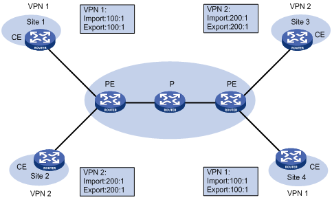
在图1-4中,PE上为VPN 1分配的VPN Target值为100:1,为VPN 2分配的VPN Target值为200:1。VPN 1的两个Site之间可以互访,VPN 2的两个Site之间也可以互访,但VPN 1和VPN 2的Site之间不能互访。
如果希望在VPN中设置中心访问控制设备,其它用户的互访都通过中心访问控制设备进行,可以使用Hub&Spoke组网方案,从而实现中心设备对两端设备之间的互访进行监控和过滤等功能。
对于这种组网,需要设置两个VPN Target,一个表示“Hub”,另一个表示“Spoke”。
各Site在PE上的VPN实例的VPN Target设置规则为:
· 连接Spoke站点(Site 1和Site 2)的Spoke-PE:Export Target为“Spoke”,Import Target为“Hub”;
· 连接Hub站点(Site 3)的Hub-PE:Hub-PE上需要使用两个接口或子接口,一个用于接收Spoke-PE发来的路由,其VPN实例的Import Target为“Spoke”;另一个用于向Spoke-PE发布路由,其VPN实例的Export Target为“Hub”。
图1-5 Hub&Spoke组网方案
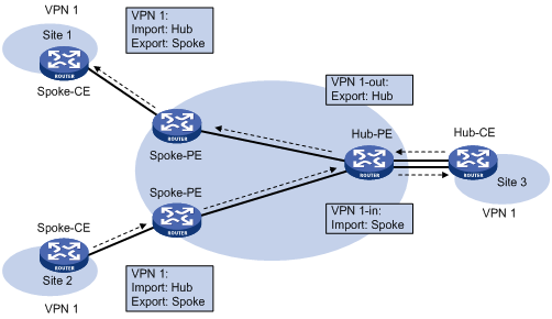
在图1-5中,Spoke站点之间的通信通过Hub站点进行(图中箭头所示为Site 2的路由向Site 1的发布过程):
· Hub-PE能够接收所有Spoke-PE发布的VPN-IPv4路由;
· Hub-PE发布的VPN-IPv4路由能够为所有Spoke-PE接收;
· Hub-PE将从Spoke-PE学到的路由发布给其他Spoke-PE,因此,Spoke站点之间可以通过Hub站点互访。
· 任意Spoke-PE的Import Target属性不与其它Spoke-PE的Export Target属性相同。因此,任意两个Spoke-PE之间不直接发布VPN-IPv4路由,Spoke站点之间不能直接互访。
如果一个VPN用户希望提供部分本VPN的站点资源给非本VPN的用户访问,可以使用Extranet组网方案。
对于这种组网,如果某个VPN需要访问共享站点,则该VPN的Export Target必须包含在共享站点的VPN实例的Import Target中,而其Import Target必须包含在共享站点VPN实例的Export Target中。
图1-6 Extranet组网方案
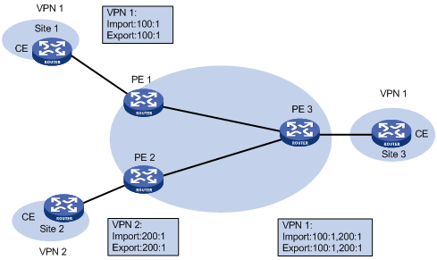
在图1-6中,VPN 1的Site 3能够被VPN 1和VPN 2访问:
· PE 3能够接受PE 1和PE 2发布的VPN-IPv4路由;
· PE 3发布的VPN-IPv4路由能够为PE 1和PE 2接受;
· 基于以上两点,VPN 1的Site 1和Site 3之间能够互访,VPN 2的Site 2和VPN 1的Site 3之间能够互访。
PE 3不把从PE 1接收的VPN-IPv4路由发布给PE 2,也不把从PE 2接收的VPN-IPv4路由发布给PE 1(IBGP邻居学来的条目是不会再发送给别的IBGP邻居),因此,VPN 1的Site 1和VPN 2的Site 2之间不能互访。
在基本MPLS L3VPN组网中,VPN路由信息的发布涉及CE和PE,P路由器只维护骨干网的路由,不需要了解任何VPN路由信息。PE路由器也只维护与它直接相连的VPN的路由信息,不维护所有VPN路由。因此,MPLS L3VPN网络具有良好的可扩展性。
VPN路由信息的发布过程包括三部分:本地CE到入口PE、入口PE到出口PE、出口PE到远端CE。完成这三部分后,本地CE与远端CE之间将建立可达路由,VPN私网路由信息能够在骨干网上发布。
下面分别对这三部分进行介绍。
CE与直接相连的PE建立邻接关系后,把本站点的VPN路由发布给PE。
CE与PE之间可以使用静态路由、RIP、OSPF、IS-IS、EBGP或IBGP。无论使用哪种路由协议,CE发布给PE的都是标准的IPv4路由。
PE从CE学到VPN路由信息后,为这些标准IPv4路由增加RD和VPN Target属性,形成VPN-IPv4路由,存放到为CE创建的VPN实例的路由表中,并触发MPLS为其分配私网标签。
入口PE通过MP-BGP把VPN-IPv4路由发布给出口PE。出口PE根据VPN-IPv4路由的Export Target属性与自己维护的VPN实例的Import Target属性,决定是否将该路由加入到VPN实例的路由表。
PE之间通过IGP来保证内部的连通性。
远端CE有多种方式可以从出口PE学习VPN路由,包括静态路由、RIP、OSPF、IS-IS、EBGP和IBGP,与本地CE到入口PE的路由信息交换相同。
实际组网应用中,某用户一个VPN的多个Site可能会连接到使用不同AS号的多个服务提供商,或者连接到一个服务提供商的多个AS。这种VPN跨越多个自治系统的应用方式被称为跨域VPN(Multi-AS VPN)。
RFC 2547bis中提出了三种跨域VPN解决方案,分别是:
· VRF-to-VRF:ASBR间使用子接口管理VPN路由,也称为Inter-Provider Option A;
· EBGP Redistribution of labeled VPN-IPv4 routes:ASBR间通过MP-EBGP发布标签VPN-IPv4路由,也称为Inter-Provider Option B;
· Multihop EBGP redistribution of labeled VPN-IPv4 routes:PE间通过MP-EBGP发布标签VPN-IPv4路由,也称为Inter-Provider Option C。
下面逐一对这些方案进行介绍。
这种方式下,两个AS的PE路由器直接相连,PE路由器同时也是各自所在自治系统的边界路由器ASBR。
作为ASBR的PE之间通过多个子接口相连,两个PE都把对方作为自己的CE设备对待,使用传统的EBGP方式向对端发布IPv4路由。报文在AS内部作为VPN报文,采用两层标签转发方式;在ASBR之间则采用普通IP转发方式。
理想情况下,每个跨域的VPN都有一对子接口与之对应,用来交换VPN路由信息。
图1-7 ASBR间使用子接口管理VPN路由组网图
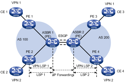
使用子接口实现跨域VPN的优点是实现简单:两个作为ASBR的PE之间不需要为跨域进行特殊配置。
缺点是可扩展性差:作为ASBR的PE需要管理所有VPN路由,为每个VPN创建VPN实例。这将导致PE上的VPN-IPv4路由数量过于庞大。并且,为每个VPN单独创建子接口也提高了对PE设备的要求。
这种方式下,两个ASBR通过MP-EBGP交换它们从各自AS的PE路由器接收的标签VPN-IPv4路由。
路由发布过程可分为以下步骤:
(1) AS 100内的PE先通过MP-IBGP方式把标签VPN-IPv4路由发布给AS 100的边界路由器PE,或发布给为ASBR PE反射路由的路由反射器;
(2) 作为ASBR的PE通过MP-EBGP方式把标签VPN-IPv4路由发布给AS 200的PE(也是AS 200的边界路由器);
(3) AS 200的ASBR PE再通过MP-IBGP方式把标签VPN-IPv4路由发布给AS 200内的PE,或发布给为PE反射路由的路由反射器。
![]()
路由反射器的介绍,请参见“三层技术-IP路由配置指导”中的“BGP”。
这种方式的ASBR需要对标签VPN-IPv4路由进行特殊处理,因此也称为ASBR扩展方式。
图1-8 ASBR间通过MP-EBGP发布标签VPN-IPv4路由组网图
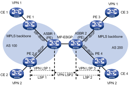
在可扩展性方面,通过MP-EBGP发布标签VPN-IPv4路由优于ASBR间通过子接口管理VPN。
采用MP-EBGP方式时,需要注意:
· ASBR之间不对接收的VPN-IPv4路由进行VPN Target过滤,因此,交换VPN-IPv4路由的各AS服务提供商之间需要就这种路由交换达成信任协议;
· VPN-IPv4路由交换仅发生在私网对等点之间,不能与公网交换VPN-IPv4路由,也不能与没有达成信任协议的MP-EBGP对等体交换VPN-IPv4路由。
前面介绍的两种方式都能够满足跨域VPN的组网需求,但这两种方式也都需要ASBR参与VPN-IPv4路由的维护和发布。当每个AS都有大量的VPN路由需要交换时,ASBR就很可能成为阻碍网络进一步扩展的瓶颈。
解决上述可扩展性问题的方案是:ASBR不维护或发布VPN-IPv4路由,PE之间直接交换VPN-IPv4路由。
两个ASBR通过MP-IBGP向各自AS内的PE路由器发布标签IPv4路由。
ASBR上不保存VPN-IPv4路由,相互之间也不通告VPN-IPv4路由。
ASBR保存AS内PE的带标签的IPv4路由,并通告给其它AS的对等体。另一个自治系统中的ASBR也通告带标签的IPv4路由。这样,在入口PE和出口PE之间建立起一条LSP。
不同AS的PE之间建立Multihop方式的EBGP连接,交换VPN-IPv4路由。
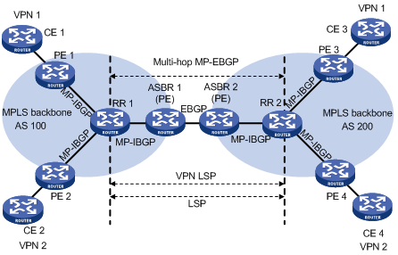
图1-9 PE间通过Multi-hop MP-EBGP发布标签VPN-IPv4路由组网图
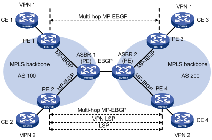
为提高可扩展性,可以在每个AS中指定一个RR(Route Reflector,路由反射器),由RR保存所有VPN-IPv4路由,与AS的PE交换VPN-IPv4路由信息。两个AS的RR之间建立跨域VPNv4连接,通告VPN-IPv4路由。如图1-10所示。
图1-10 采用RR的跨域VPN OptionC方式组网图
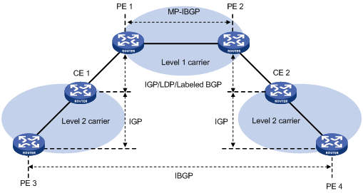
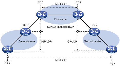
MPLS L3VPN服务提供商的用户可能也是一个服务提供商。这种情况下,前者称为提供商运营商(Provider Carrier)或一级运营商(First Carrier),后者称为客户运营商(Customer Carrier)或二级运营商(Second Carrier)。这种组网模型称为运营商的运营商(Carriers’ carriers),低级别的SP作为更高级别SP的CE。
为保持良好的可扩展性,一级运营商并不引入二级运营商连接的用户网络的路由,只引入为不同站点的二级运营商交换报文的路由。二级运营商连接的用户网络的路由通过在相关二级运营商路由器间建立BGP会话交换。这可以大大减少一级运营商网络中需要维护的路由数量。
与普通MPLS L3VPN相比,配置运营商的运营商的主要区别在于一级运营商PE接入二级运营商CE这一部分:
· 如果一级运营商PE与二级运营商CE位于同一个AS内,则它们之间配置IGP和LDP;
· 如果一级运营商PE与二级运营商CE位于不同的AS,则它们之间配置MP-EBGP。MP-EBGP为PE与CE之间交换的路由分配标签。
无论哪种情况,CE上都需要使能MPLS。并且,CE上虽然有二级运营商的VPN路由,但它们并不把这些路由发布给一级运营商的PE,只在二级运营商PE之间交换。
二级运营商可能只是普通ISP,也可能是MPLS L3VPN服务提供商。
二级运营商是普通ISP时,其PE不需要运行MPLS,与CE之间运行IGP。PE 3和PE 4之间通过IBGP会话交换二级运营商的VPN路由。如图1-11所示。
二级运营商是MPLS L3VPN服务提供商时,其PE也需要运行MPLS,与CE之间运行IGP和LDP。PE 3和PE 4之间通过MP-IBGP会话交换二级运营商的VPN路由。如图1-12所示。
![]()
如果一级运营商和二级运营商之间存在等价路由,则建议在一级运营商和二级运营商之间建立对应的等价LSP。
在基本的MPLS L3VPN模型中,由运营商经营MPLS VPN骨干网,通过PE设备提供VPN服务。VPN用户通过CE设备与运营商的PE设备互连,接入MPLS VPN网络,实现属于用户VPN的不同Site之间的通信。在这种情况下,用户网络是普通的IP网络,VPN用户不能再划分子VPN。
实际组网中,VPN用户网络复杂多样,繁简不同。当VPN用户内部需要进一步划分多个VPN时,传统的解决方案是直接在运营商的PE设备上配置用户内部的VPN。这种方案实现简单,缺点是将导致PE上承载的VPN数量急剧增加,并且,如果用户内部需要调整VPN关系,也必须通过运营商操作。这不仅增加了网络的运营成本,也带来了管理和安全方面的问题。
嵌套VPN是一种更为完善的解决方案,它的主要思想是在普通MPLS L3VPN的PE和CE之间传递VPNv4路由,由用户管理自己内部的VPN划分,运营商不参与用户内部VPN的管理。如图1-13所示,用户在运营商MPLS VPN网络上所属的VPN为VPN A,在用户网络内部划分子VPN:VPN A-1和VPN A-2。运营商PE设备把用户网络当作普通VPN用户对待,不参与子VPN的划分。VPN用户的CE设备(CE 1、CE 2、CE 7和CE 8)和运营商PE设备之间传递包括子VPN路由信息的VPNv4路由,从而实现用户网络内部子VPN路由信息的传递。
图1-13 嵌套VPN组网应用
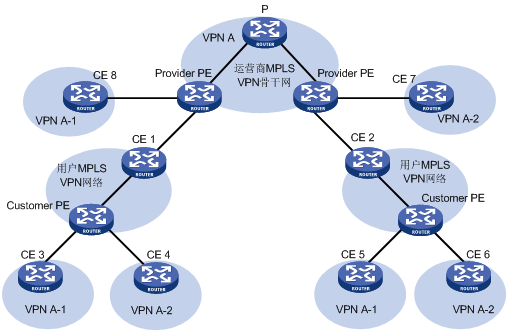
嵌套VPN中,路由信息的传播过程为:
(1) 运营商的PE设备与VPN用户的CE设备交互VPNv4路由,VPNv4路由携带用户内部的VPN信息。
(2) 运营商的PE设备收到VPNv4路由后,保留用户内部的VPN信息,并附加用户在运营商网络上的MPLS VPN属性,即将该VPNv4路由的RD更换为用户所处运营商网络VPN的RD,同时将用户所处运营商网络VPN的ERT(Export Route-target,引出路由标识)添加到路由的扩展团体属性列表中。运营商的PE设备维护用户内部的VPN信息。
(3) 运营商的PE设备向其他运营商PE设备发布这些携带综合VPN信息的VPNv4路由。
(4) 其他的运营商PE设备收到VPNv4路由后,与本地的VPN进行匹配,每个VPN接收属于自己的路由,然后将路由扩散到自己连接的子VPNCE设备(如图1-13中的CE 3、CE 4、CE 5和CE 6):如果运营商PE和CE设备之间是IPv4连接,直接扩散IPv4路由;如果和CE设备之间是VPNv4连接,表示通过私网连接的是一个用户MPLS VPN网络,向CE扩散VPNv4路由。
嵌套VPN技术的主要优点是:
· 实现了VPN聚合功能,可以把用户的多个内部VPN聚合成一个用户VPN,接入运营商的MPLS VPN网络;
· 支持对称组网方式和非对称组网方式,即属于同一VPN用户的不同Site包括的用户内部VPN数目可以相同,也可以不同;
· 支持用户内部VPN的多层嵌套。
嵌套VPN技术降低了用户接入VPN网络的复杂度和成本,为用户提供多样化的VPN组网方式,实现了用户对内部VPN以及多层VPN之间的互访权限控制管理。
(1) 分层模型与平面模型
在MPLS L3VPN解决方案中,PE设备最为关键,它完成两方面的功能:首先是为用户提供接入功能,这需要PE具有大量接口;然后是管理和发布VPN路由,处理用户报文,这需要PE设备具有大容量存储和高转发能力。
目前的网络设计大多采用经典的分层结构,例如,城域网的典型结构是三层模型:核心层、汇聚层、接入层。从核心层到接入层,对设备的性能要求依次下降,网络的规模则依次扩大。
而MPLS L3VPN是一种平面模型,对网络中所有PE设备的性能要求相同,当网络中某些PE在性能和可扩展性方面存在问题时,整个网络的性能和可扩展性将受到影响。
由于MPLS L3VPN的平面模型与典型的分层网络模型不相符,在每一个层次上部署PE都会遇到扩展性问题,不利于大规模部署VPN。
(2) HoVPN
为解决可扩展性问题,MPLS L3VPN必然要从平面模型转变为分层模型。
在MPLS L3VPN领域,HoVPN(Hierarchy of VPN,分层VPN)解决方案的提出,实现了将PE的功能分布到多个PE设备上,多个PE承担不同的角色,并形成层次结构,共同完成一个PE的功能。
HoVPN对处于较高层次的设备的路由能力和转发性能要求较高,而对处于较低层次的设备的相应要求也较低,符合典型的分层网络模型。
(1) HoVPN的基本结构
图1-14 HoVPN的基本结构
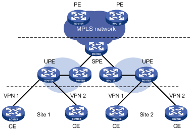
在图1-14中,直接连结用户的设备称为UPE(Underlayer PE or User-end PE,下层PE或用户侧PE);连结UPE并位于网络内部的设备称为SPE(Superstratum PE or Sevice Provider-end PE,上层PE或运营商侧PE)。
多个UPE与SPE构成分层式PE,共同完成传统上一个PE的功能。
![]()
HoVPN把PE的功能分层实现,因此,这种解决方案有时也被称为HoPE(Hiberarchy of PE,分层PE)。
SPE与UPE的分工是:
· UPE主要完成用户接入功能。UPE维护其直接相连的VPN Site的路由,但不维护VPN中其它远程Site的路由或仅维护它们的聚合路由;UPE为其直接相连的Site的路由分配内层标签,并通过MP-BGP随VPN路由发布此标签给SPE;
· SPE主要完成VPN路由的管理和发布。SPE维护其通过UPE连接的VPN所有路由,包括本地和远程Site的路由,SPE将路由信息发布给UPE,并携带标签。SPE发布的路由信息可以是VPN实例的缺省路由(或聚合路由),也可以是通过路由策略的路由信息。通过后者可以实现对同一VPN下不同站点之间互访的控制。
由于分工的不同,对SPE和UPE的要求也不同:SPE的路由表容量大,转发性能强,但接口资源较少;UPE的路由容量和转发性能较低,但接入能力强。HoVPN充分利用了SPE的性能和UPE的接入能力。
需要说明的是,SPE和UPE是相对的概念。在多个层次的PE结构中,上层PE相对于下层就是SPE,下层PE相对于上层就是UPE。
分层式PE从外部来看同传统上的PE没有区别,可以同普通PE共存于一个MPLS网络。
(2) SPE-UPE
SPE和UPE之间运行MP-BGP,可以是MP-IBGP,也可以是MP-EBGP,这取决于UPE和SPE是否属于同一个AS。
采用MP-IBGP时,为了在IBGP对等体之间通告路由,SPE将作为路由反射器,把来自IBGP对等体UPE的VPN路由发布给IBGP对等体SPE,但SPE不作为其它PE的路由反射器。
(3) HoVPN的嵌套与扩展
HoVPN支持分层式PE的嵌套:
· 一个分层式PE可以作为UPE,同另一个SPE组成新的分层式PE;
· 一个分层式PE可以作为SPE,同多个UPE组成新的分层式PE;
· 以上这种嵌套可以多次进行。
通过分层式PE的嵌套,理论上可以将VPN无限扩展与延伸。
图1-15 分层式PE的嵌套
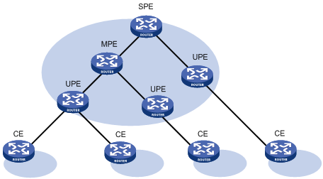
图1-15是一个三层的分层式PE,称中间的PE为MPE(Middle-level PE)。SPE和MPE之间,以及MPE和UPE之间,均运行MP-BGP。
![]()
“MPE”这种说法只是为了表述方便,在HoVPN模型中并没有MPE。
MP-BGP为上层PE发布下层PE上的所有VPN路由,为下层PE发布上层PE的VPN实例缺省路由或通过路由策略的VPN路由。
SPE维护了这个分层式PE接入的所有Site的VPN路由,路由数目最多;UPE只维护它所直接连接的Site的VPN路由,路由数目最少;MPE的路由数目介于SPE和UPE之间。
![]()
本节重点介绍OSPF对VPN的扩展,如果需要了解OSPF的基本知识,请参见“三层技术-IP路由配置指导”中的“OSPF”。
OSPF是应用广泛的一种IGP协议,很多情况下,VPN客户端通过BGP对等体连接,客户端内部则经常以OSPF作为内部路由协议。如果能够在PE-CE之间使用OSPF,则CE上就不需要再为到PE的连接支持其它路由协议,从而简化CE的管理和配置。并且,如果客户需要通过传统的OSPF骨干区域提供MPLS L3VPN服务,在PE和CE之间使用OSPF可以简化这种转换。
为了在PE-CE间运行OSPF,PE必须支持OSPF多实例,每个OSPF实例与一个VPN实例对应,使用自己的接口、路由表。
下面具体介绍在PE-CE间配置OSPF需要了解的知识。
(1) PE和CE间的OSPF区域配置
PE与CE之间的OSPF区域可以是非骨干区域,也可以是骨干区域。
在OSPF VPN扩展应用中,MPLS VPN骨干网被看作是骨干区域area 0。由于OSPF要求骨干区域连续,因此,所有VPN站点的area 0必须与MPLS VPN骨干网相连。
即:如果VPN站点存在OSPF area 0,则CE接入的PE必须通过area 0与这个VPN站点的骨干区域相连(可以通过Virtual-link实现逻辑上的连通)。
(2) BGP/OSPF交互
在PE-CE间运行OSPF后,PE与PE通过BGP发布VPN路由,PE通过OSPF向CE发布VPN路由。
对于普通OSPF,即使两个不同站点属于同一VPN,它们也会被看作属于不同的自治系统。这样,在一个站点学到的路由,将被作为外部路由传送给另一站点。这种处理方式导致了比较高的OSPF路由协议流量,并带来了一些原本可以避免的网络管理问题。
目前的OSPF可以解决上述问题。通过适当配置,运行OSPF的不同站点之间彼此看作是直接相连的。这样,PE路由器交换OSPF路由信息时就好像是通过一条专线相连。改善了网络管理并使OSPF的应用更为有效。
以图1-16为例,PE 1和PE 2通过MPLS骨干网相连,CE 11、CE 21和CE 22都属于VPN 1。假设图中所有路由器属于同一个域,即CE 11、CE 21、CE 22属于同一个OSPF域(OSPF domain)。
VPN 1路由的发布过程可以描述为:首先在PE 1上将CE 11的OSPF路由引入BGP;然后通过BGP将这些VPN路由发布给PE 2;在PE 2上将BGP的VPN路由引入到OSPF,再发布给CE 21和CE 22。
图1-16 OSPF在VPN中的使用
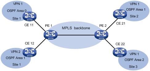
如果使用标准的BGP/OSPF交互过程,PE 2将把BGP VPN路由通过Type5 LSAs(即ASE LSAs)发布给CE 21和CE 22。但CE 11与CE 21、CE 22是同一个OSPF域,它们之间的路由发布应该使用Type3 LSAs,即区域间路由。
为了解决上述问题,PE使用一种经过修改的BGP/OSPF交互过程(简称为BGP/OSPF互操作功能),发布从一个Site到另一个Site的路由,将这种路由与真正的AS-External路由进行区分。这一过程需要BGP使用扩展团体属性,携带可以标识OSPF属性的信息。
在实现中,要求每个OSPF域有一个可配置的域ID(Domain ID)。一般建议:同一个VPN的所有OSPF进程要么配置一个相同的域ID,要么都使用缺省的域ID。这样在收到BGP的VPN路由时,域ID相同的是来自同一VPN实例的路由。
(3) 路由环的检测
假设PE与CE之间通过OSPF骨干区域相连,且同一个VPN站点(Site)连接到多个不同PE。这种情况下,当一个PE通过LSA向VPN站点发布从MPLS/BGP学的BGP VPN路由时,LSA可能被另一个PE接收到,造成路由环。
为了防止产生路由环,对于从MPLS/BGP学到的BGP VPN路由,无论PE与CE间是否通过OSPF骨干区域相连,PE在生成Type3 LSA时,都会设置标志位DN。PE路由器的OSPF进程在进行路由计算时,忽略DN置位的Type3 LSAs。
如果PE需要向CE发布一条来自其它OSPF域的路由,则PE应表明自己是ASBR,并将该路由作为Type5 LSA发布。
通常情况下,BGP对等体之间通过BGP扩展团体属性在MPLS VPN骨干网上承载路由信息。另一端PE上运行的OSPF可利用这些信息来生成PE到CE的Type3 summary LSA,这些路由是区域间路由。
如图1-17所示:在OSPF的PE-CE连接中,同一个OSPF区域中有两个Site连接到不同的PE,两个Site属于同一个VPN,它们之间存在一条区域内OSPF链路(backdoor link)。这种情况下,通过PE连接两个Site的路由将作为区域间路由(Inter-Area Route),由于其优先级低于经过backdoor链路的区域内路由(Intra-Area Route),不会被OSPF优选。
图1-17 Sham-link应用示意图
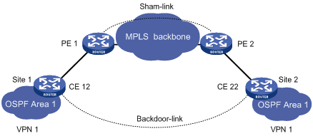
上述情况导致VPN流量总是通过backdoor路由转发,而不走骨干网。为了避免这一问题,可以在PE路由器之间建立OSPF伪连接(Sham-link),使经过MPLS VPN骨干网的路由也成为OSPF区域内路由。
Sham-link作为区域内的一条点到点链路,包含在Type1 LSA中发布。用户可以通过调整度量值在Sham-link和backdoor链路之间进行选路。
Sham-link被看成是两个VPN实例之间的链路,每个VPN实例中必须有一个Sham-link的端点地址,它是PE路由器上VPN地址空间中的一个有32位掩码的Loopback接口地址。同一个OSPF进程的Sham-link可以共用端点地址,但不同OSPF进程不能拥有两条端点地址完全相同的Sham-link。
Sham-link的端点地址被BGP作为VPN-IPv4地址发布。如果路由经过了Sham-link,它就不能再以VPN-IPv4路由的形式被引入到BGP。
Sham-link可以在任何区域配置。Sham-link需要手工配置,并且,本端VPN实例中必须有到Sham-link目的地址的路由。
![]()
配置OSPF伪连接时,需要在PE上配置BGP引入OSPF的私网路由,但不能配置OSPF引入BGP路由,否则会引起路由环路。
在MPLS L3VPN中,如果PE和CE之间运行EBGP,由于BGP使用AS号检测路由环路,为保证路由信息的正确发送,需要为物理位置不同的站点分配不同的AS号。
如果物理分散的CE复用相同的AS号,就应该在PE上配置BGP的AS号替换功能。此功能是BGP的出口策略,在发布路由时有效。
使能了BGP的AS号替换功能后,当PE向指定对等体中的CE发布路由时,如果路由的AS_PATH中有与CE相同的AS号,将被替换成PE的AS号后再发布。
![]()
使能BGP的AS号替换功能后,PE向对等体组中所有已建立连接的CE重新发送所有路由,并对发送路由中的AS_PATH属性按上述规则替换。
图1-18 BGP AS号替换和SoO属性应用示意图
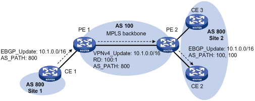
在图1-18中,Site 1和Site 2都使用AS号800,在PE 2上使能针对CE 2的AS号替换功能。当CE 1发来的Update信息从PE 2发布给CE 2时,PE 2发现AS_PATH中存在与CE 2相同的AS号800,就把它替换为自己的AS号100,这样,CE 2就可以正确接收CE 1的路由信息。
PE使用不同接口连接同一站点的多个CE时,如图1-18中的CE 2和CE 3,使用BGP的AS号替换功能,会导致路由环路。使能针对CE 2的AS号替换功能后,CE 3发布的路由会通过PE 2和CE 2再次发布到Site 2,导致路由环路。此时,通过在PE 2上对从CE 2和CE 3学习的路由应用路由策略,为学习到的路由添加相同的SoO属性,可以防止PE 2将CE 3发布的路由再次通过CE 2发布给Site 2,避免路由环路。
表1-1 MPLS L3VPN配置任务简介
|
配置任务 |
详细配置 |
说明 |
|
配置基本MPLS L3VPN |
完成基本MPLS L3VPN配置后,即可实现通过MPLS技术构建简单的VPN网络 如果部署一些特殊的MPLS L3VPN组网方案,例如跨域VPN、嵌套VPN等,除了配置基本MPLS L3VPN外,还需要根据相应章节进行其他的配置 |
|
|
配置跨域VPN |
||
|
配置嵌套VPN |
||
|
配置HoVPN |
||
|
配置OSPF伪连接 |
||
|
配置BGP的AS号替换和SoO属性 |
配置MPLS L3VPN的关键在于管理VPN私网路由在MPLS骨干网上的发布,包括PE-CE间的路由发布管理以及PE-PE间的路由发布管理。
表1-2 基本MPLS L3VPN配置任务简介
|
配置任务 |
说明 |
详细配置 |
|
|
配置VPN实例 |
创建VPN实例 |
必选 |
|
|
配置VPN实例与接口关联 |
必选 |
||
|
配置VPN实例的路由相关属性 |
可选 |
||
|
配置VPN实例的隧道策略 |
可选 |
||
|
配置LDP实例 |
可选 |
||
|
配置PE-CE间的路由交换 |
必选 |
||
|
配置PE-PE间的路由交换 |
必选 |
||
|
配置BGP-VPNv4子地址族下的路由特性 |
可选 |
||
在配置基本MPLS L3VPN之前,需完成以下任务:
· 对MPLS骨干网(PE、P)配置IGP,实现骨干网的IP连通性
· 对MPLS骨干网(PE、P)配置MPLS基本能力
· 对MPLS骨干网(PE、P)配置MPLS LDP,建立LDP LSP
VPN实例不仅可以隔离VPN私网路由与公网路由,还可以隔离不同VPN实例的路由,这一特点使得VPN实例的使用不限于MPLS L3VPN。
配置VPN实例的操作是在PE或MCE设备上进行的。
VPN实例在实现中与Site关联。VPN实例不是直接对应于VPN,一个VPN实例综合了和它所对应Site的VPN成员关系和路由规则。
表1-3 创建VPN实例
|
操作 |
命令 |
说明 |
|
进入系统视图 |
system-view |
- |
|
创建VPN实例,并进入VPN实例视图 |
ip vpn-instance vpn-instance-name |
必选 |
|
配置VPN实例的保留VLAN |
reserve-vlan vlan-id |
必选 |
|
配置VPN实例的RD |
route-distinguisher route-distinguisher |
必选 一个VPN实例只有配置了RD后才会生效 |
|
配置VPN实例的描述信息 |
description text |
可选 描述信息用于描述VPN实例,可以用来记录VPN实例与某个VPN的关系等信息 |
VPN实例配置完成后,还需要与连接CE的接口进行关联。支持MPLS LDP能力的接口类型都可以与VPN实例相关联。具体接口类型请参见“MPLS配置指导”中的“MPLS基础”。
表1-4 配置VPN实例与接口关联
|
操作 |
命令 |
说明 |
|
进入系统视图 |
system-view |
- |
|
进入要关联接口的接口视图 |
interface interface-type interface-number |
- |
|
将当前接口与VPN实例关联 |
ip binding vpn-instance vpn-instance-name |
必选 缺省情况下,接口不关联任何VPN实例 |
![]()
执行ip binding vpn-instance命令将删除接口上已经配置的IP地址,因此需要重新配置接口的IP地址。
VPN路由的发布控制过程如下:
· 当从CE学习到的一条VPN路由引入BGP时,BGP为它关联一个VPN Target扩展团体属性列表,通常这个列表是与CE相关联的VPN实例的输出路由属性列表。
· VPN实例根据VPN Target中import-extcommunity决定可被接受并引入此VPN实例的路由。
· VPN实例根据VPN Target中的export-extcommunity对向外发布的路由进行VPN Target属性的修改。
表1-5 配置VPN实例的路由相关属性
|
操作 |
命令 |
说明 |
|
进入系统视图 |
system-view |
- |
|
进入VPN实例视图 |
ip vpn-instance vpn-instance-name |
- |
|
进入IPv4 VPN视图 |
ipv4-family |
可选 |
|
配置VPN Target |
vpn-target vpn-target&<1-8> [ both | export-extcommunity | import-extcommunity ] |
必选 |
|
配置支持的最大路由数 |
routing-table limit number { warn-threshold | simply-alert } |
可选 |
|
应用入方向路由策略 |
import route-policy route-policy |
可选 缺省情况下,接收所有VPN Target属性匹配的路由 |
|
应用出方向路由策略 |
export route-policy route-policy |
可选 缺省情况下,不对发布的路由进行过滤 |
![]()
· VPN实例视图下配置的路由相关属性既可以用于IPv4 VPN,也可以用于IPv6 VPN。
· 既可以在VPN实例视图下,也可以在IPv4 VPN视图下,配置IPv4 VPN的路由相关属性。如果同时在两个视图下配置了路由相关属性,则IPv4 VPN采用IPv4 VPN视图下配置的路由相关属性。
· 命令vpn-target最多可以配置8个VPN Target;一个VPN实例最多可以配置64个VPN Target。
· 可以配置一个VPN实例支持的最大路由数,以防止PE路由器的入接口有过多的路由。
· 为VPN实例配置路由策略之前必须已经创建了路由策略,否则无法对接收和发布的路由进行过滤。
在网络中存在多条、多种类型的隧道时,可以通过配置隧道策略对选择的隧道种类和隧道数目进行限制。
通过tunnel select-seq命令,可以配置隧道的优先级顺序和负载分担条数。
通过preferred-path命令可以配置优选路径,每条优选路径对应一个隧道接口,指定通过哪个隧道接口转发流量。
应用隧道策略后,隧道的选择方式为:
(1) 从编号最小的优选路径开始匹配,如果对端PE地址和任何优选路径的隧道目的地址都不同,则根据tunnel select-seq命令配置的隧道优先级顺序和负载分担条数选择隧道。如果没有配置tunnel select-seq命令,则根据缺省的隧道策略选择隧道,即按照LSP隧道->CR-LSP隧道的优先级顺序选择隧道,负载分担条数为1。
(2) 如果对端PE地址和某条优选路径的隧道目的地址相同,则匹配成功。此优选路径指定的隧道可用时,不再匹配后续的隧道策略规则,使用该优选路径指定的隧道接口转发流量。
(3) 匹配的优选路径指定的隧道不可用时(例如,隧道接口down、隧道下配置的ACL规则不允许转发该流量等原因导致隧道不可用),如果该优选路径中没有指定disable-fallback参数,则继续匹配后续的隧道策略规则;如果该优选路径中指定了disable-fallback参数,则不再匹配后续的隧道策略规则,隧道查找失败。
表1-6 配置VPN实例的隧道策略
|
操作 |
命令 |
说明 |
|
进入系统视图 |
system-view |
- |
|
创建隧道策略,并进入隧道策略视图 |
tunnel-policy tunnel-policy-name |
必选 |
|
配置通过隧道接口转发报文的优选路径 |
preferred-path number interface tunnel tunnel-number [ disable-fallback ] |
可选 缺省情况下,不存在任何优选路径 |
|
配置隧道的优先级顺序和负载分担条数 |
tunnel select-seq { cr-lsp | lsp } * load-balance-number number |
可选 缺省情况下,按照LSP隧道->CR-LSP隧道的优先级顺序选择隧道,负载分担条数为1 |
|
退回系统视图 |
quit |
- |
|
进入VPN实例视图 |
ip vpn-instance vpn-instance-name |
必选 |
|
进入IPv4 VPN视图 |
ipv4-family |
可选 |
|
配置VPN实例的隧道策略 |
tnl-policy tunnel-policy-name |
必选 缺省情况下,按照LSP隧道->CR-LSP隧道的优先级顺序选择隧道,负载分担条数为1 |
![]()
· 配置的隧道类型不止一种,且负载分担的条数多于单个类型包含的隧道个数时,会使用不同类型的隧道一起进行负载分担。
· 一个隧道策略下最多可以配置64条优选路径。不同优选路径对应的隧道接口的目的地址可以相同。隧道接口的隧道类型必须为MPLS TE。
· 在配置隧道优先级顺序时,隧道类型越靠近关键字select-seq的,其优先级越高。例如:如果配置了命令tunnel select-seq lsp cr-lsp load-balance-number 1,在没有LSP的情况下,VPN将使用CR-LSP隧道,当LSP建立后,VPN将选用LSP。
· VPN实例视图下配置的隧道策略既可以用于IPv4 VPN,也可以用于IPv6 VPN。
· 既可以在VPN实例视图下,也可以在IPv4 VPN视图下,配置IPv4 VPN的隧道策略。如果同时在两个视图下配置了隧道策略,则IPv4 VPN采用IPv4 VPN视图下配置的隧道策略。
· 为VPN实例配置隧道策略之前必须先创建隧道策略,否则将采用缺省策略,即按照LSP隧道-> CR-LSP隧道的优先级顺序选择隧道,负载分担条数为1。
LDP实例应用于运营商的运营商(Carriers’ carriers)组网模型中。
本配置任务用来使能VPN实例的LDP能力,创建LDP实例,并在MPLS-LDP-VPN实例视图下为VPN实例配置LDP参数。
表1-7 配置LDP实例
|
操作 |
命令 |
说明 |
|
进入系统视图 |
system-view |
- |
|
使能指定VPN实例的LDP能力,创建LDP实例,并进入MPLS-LDP-VPN实例视图 |
mpls ldp vpn-instance vpn-instance-name |
必选 缺省情况下,未使能VPN实例的LDP能力 |
|
配置除LDP GR外的其他LDP参数 |
详细配置请参见“MPLS配置指导”中的“MPLS基础” |
可选 |
![]()
· 除了LDP GR特性外,MPLS LDP视图下的命令都可以在MPLS-LDP-VPN实例视图下使用。MPLS LDP的详细介绍请参见“MPLS配置指导”中的“MPLS基础”。
· 对于使能LDP能力的接口,MPLS-LDP-VPN实例视图下的配置只影响绑定VPN实例的接口;而MPLS LDP视图下的配置对绑定到VPN实例的接口没有影响。为LDP实例配置传输地址时,也必须使用绑定到VPN实例的接口的IP地址。
· 对于私网侧的LDP邻居关系,缺省情况下是使用使能LDP能力的接口地址建立的;而公网上的LDP邻居关系,缺省情况下是使用LDP实例的LSR ID建立的。
PE-CE间路由交换可以使用静态路由、RIP、OSPF、IS-IS、EBGP和IBGP路由协议。根据实际组网情况选择一种进行配置即可。
在配置PE-CE间路由交换之前,需要先完成以下任务:
· 在CE上配置连接PE接口的IP地址
· 在PE上配置连接CE接口的IP地址
表1-8 配置PE-CE间使用静态路由
|
操作 |
命令 |
说明 |
|
进入系统视图 |
system-view |
- |
|
为指定VPN实例配置静态路由 |
ip route-static dest-address { mask | mask-length } { gateway-address | interface-type interface-number [ gateway-address ] | vpn-instance d-vpn-instance-name gateway-address } [ preference preference-value ] [ tag tag-value ] [ description description-text ] |
必选 该配置在PE上进行,CE上的配置方法与普通静态路由相同 |
|
ip route-static vpn-instance s-vpn-instance-name&<1-5> dest-address { mask | mask-length } { gateway-address [ public ] | interface-type interface-number [ gateway-address ] | vpn-instance d-vpn-instance-name gateway-address } [ preference preference-value ] [ tag tag-value ] [ description description-text ] |
![]()
有关静态路由的配置请参见“三层技术-IP路由配置指导”中的“静态路由”。
一个RIP进程只能属于一个VPN实例。如果在启动RIP进程时不绑定到VPN实例,则该进程属于公网进程。
表1-9 配置PE-CE间使用RIP
|
操作 |
命令 |
说明 |
|
进入系统视图 |
system-view |
- |
|
创建PE-CE间的RIP实例,并进入RIP视图 |
rip [ process-id ] vpn-instance vpn-instance-name |
必选 该配置在PE上进行,CE上配置普通RIP即可 |
|
在指定网段接口上使能RIP |
network network-address |
必选 缺省情况下,接口上的RIP功能处于关闭状态 |
![]()
有关RIP的介绍和详细配置,请参见“三层技术-IP路由配置指导”中的“RIP”。
VPN实例绑定的OSPF进程中不使用系统视图下配置的公网Router ID,因此用户需要在启动进程时手工配置Router ID,或者所要绑定的VPN实例中至少有一个接口配置了IP地址。
一个OSPF进程只能属于一个VPN实例。如果在启动OSPF进程时不绑定到VPN实例,则该进程属于公网进程。
表1-10 配置PE-CE间使用OSPF
|
操作 |
命令 |
说明 |
|
进入系统视图 |
system-view |
- |
|
创建PE-CE间的OSPF实例,并进入OSPF视图 |
ospf [ process-id | router-id router-id | vpn-instance vpn-instance-name ] * |
必选 该配置在PE上进行,CE上配置普通OSPF即可 |
|
配置OSPF域标识符 |
domain-id domain-id [ secondary ] |
可选 缺省情况下,OSPF域标识符为0 该配置在PE上进行,CE上配置普通OSPF即可 |
|
配置OSPF扩展团体属性的类型编码 |
ext-community-type { domain-id type-code1 | router-id type-code2 | route-type type-code3 } |
可选 缺省情况下,OSPF扩展团体属性Domain ID的类型编码是0x0005,Router ID的类型编码是0x0107,Route Type的类型编码是0x0306 该配置在PE上进行 |
|
配置OSPF区域,进入OSPF区域视图 |
area area-id |
必选 缺省情况下,没有配置OSPF区域 |
|
配置区域所包含的网段并在指定网段的接口上使能OSPF |
network ip-address wildcard-mask |
必选 缺省情况下,接口不属于任何区域且OSPF功能处于关闭状态 |
![]()
删除VPN实例后,相关的所有OSPF进程也将全部被删除。
每个OSPF进程只能配置一个域ID,不同进程的域ID相互没有影响。不同VPN的PE的OSPF进程域ID配置没有限制。但同一VPN的所有OSPF进程应配置相同的域ID,以保证路由发布的正确性。
OSPF进程的域ID包含在此进程生成的路由中,在将OSPF路由引入BGP中时, 域ID被附加到BGP VPN路由上,作为BGP的扩展团体属性传递。
![]()
· 配置OSPF实例后,需要启动OSPF,具体配置与普通的OSPF相同。
· 有关OSPF的介绍和详细配置,请参见“三层技术-IP路由配置指导”中的“OSPF”。
一个IS-IS进程只能属于一个VPN实例。如果在启动IS-IS进程时不绑定到VPN实例,则该进程属于公网进程。
表1-11 配置PE-CE间使用IS-IS
|
操作 |
命令 |
说明 |
|
进入系统视图 |
system-view |
- |
|
创建PE-CE间的IS-IS实例,并进入IS-IS视图 |
isis [ process-id ] vpn-instance vpn-instance-name |
必选 该配置在PE上进行,CE上配置普通IS-IS即可 |
|
配置网络实体名称 |
network-entity net |
必选 缺省情况下,没有配置网络实体名称 |
|
退回系统视图 |
quit |
- |
|
进入接口视图 |
interface interface-type interface-number |
- |
|
使能接口IS-IS并指定要关联的IS-IS进程号 |
isis enable [ process-id ] |
必选 缺省情况下,接口上没有使能IS-IS |
![]()
有关IS-IS的介绍和详细配置,请参见“三层技术-IP路由配置指导”中的“IS-IS”。
(1) PE上的配置
表1-12 PE上的配置
|
操作 |
命令 |
说明 |
|
进入系统视图 |
system-view |
- |
|
进入BGP视图 |
bgp as-number |
- |
|
进入BGP-VPN实例视图 |
ipv4-family vpn-instance vpn-instance-name |
必选 |
|
将CE配置为VPN私网EBGP对等体 |
peer { group-name | ip-address } as-number as-number |
必选 |
|
引入本端CE路由 |
import-route protocol [ process-id ] [ med med-value | route-policy route-policy-name ] * |
必选 PE需要将到本端CE的路由引入VPN路由表中,以发布给对端PE |
|
配置对发布的路由信息进行过滤 |
filter-policy { acl-number | ip-prefix ip-prefix-name } export [ direct | isis process-id | ospf process-id | rip process-id | static ] |
可选 缺省情况下,不对发布的路由信息进行过滤 |
|
配置对接收的路由信息进行过滤 |
filter-policy { acl-number | ip-prefix ip-prefix-name } import |
可选 缺省情况下,不对接收的路由信息进行过滤 |
|
配置允许本地AS号在所接收的路由的AS_PATH属性中出现,并可同时配置允许重复的次数 |
peer { group-name | ip-address } allow-as-loop [ number ] |
可选 用于Hub&Spoke组网方案 |
![]()
通常情况下,BGP通过AS号检测路由环路。但在Hub&Spoke组网方式下,如果在PE和CE之间运行EBGP,当PE将路由信息通告给CE时带上本自治系统的AS号,再从CE接收路由更新时,路由更新消息中会带有本自治系统的AS号,这样PE就不能接收这条路由更新信息,此时需要配置允许路由环路。
(2) CE上的配置
表1-13 CE上的配置
|
操作 |
命令 |
说明 |
|
进入系统视图 |
system-view |
- |
|
进入BGP视图 |
bgp as-number |
- |
|
将PE配置为EBGP对等体 |
peer { group-name | ip-address } as-number as-number |
必选 |
|
配置路由引入 |
import-route protocol [ process-id ] [ med med-value | route-policy route-policy-name ] * |
可选 CE需要将自己所能到达的VPN网段地址发布给接入的PE,通过PE发布给对端CE |
![]()
· 配置BGP VPN实例后,VPN实例中的BGP路由交换与普通的BGP相同。
· BGP实例视图下配置任务与BGP视图下的相同,有关介绍和详细配置,请参见“三层技术-IP路由配置指导”中的“BGP”。
· BGP的配置中有对等体和对等体组的配置,有关介绍和详细说明请参见“三层技术-IP路由配置指导”中的“BGP”。本章中不将对等体和对等体组加以区分。
![]()
PE和CE之间使用IBGP路由协议只适用于普通的MPLS L3VPN组网环境,Extranet、跨域VPN、运营商的运营商、嵌套VPN和HoVPN等组网中,PE和CE之间不能配置IBGP。
(1) PE上的配置
表1-14 PE上的配置
|
操作 |
命令 |
说明 |
|
进入系统视图 |
system-view |
- |
|
进入BGP视图 |
bgp as-number |
- |
|
进入BGP-VPN实例视图 |
ipv4-family vpn-instance vpn-instance-name |
必选 |
|
将CE配置为VPN私网IBGP对等体 |
peer { group-name | ip-address } as-number as-number |
必选 |
|
将CE配置为路由反射器的客户端 |
peer { group-name | ip-address } reflect-client |
可选 缺省情况下,没有配置路由发射器及其客户端 |
|
允许客户到客户的路由反射 |
reflect between-clients |
可选 缺省情况下,允许客户到客户的路由反射 如果客户之间是全连接的,则不需要配置路由反射 |
|
为路由反射器配置群ID |
reflector cluster-id { cluster-id | ip-address } |
可选 缺省情况下,每个路由反射器都使用自己的Router ID作为群ID 如果一个群中配置了多个路由反射器,请使用本命令为所有的路由反射器配置相同的群ID,以避免产生路由环路 |
|
配置对发布的路由信息进行过滤 |
filter-policy { acl-number | ip-prefix ip-prefix-name } export [ direct | isis process-id | ospf process-id | rip process-id | static ] |
可选 缺省情况下,不对发布的路由信息进行过滤 |
|
配置对接收的路由信息进行过滤 |
filter-policy { acl-number | ip-prefix ip-prefix-name } import |
可选 缺省情况下,不对接收的路由信息进行过滤 |
![]()
· 缺省情况下PE不会向IBGP对等体(包括VPNv4的IBGP对等体)发送从IBGP对等体CE学习的路由,只有将CE配置为路由反射器的客户端后,才能向其它IBGP对等体发送从该CE学习的路由。
· 可以在多个视图下执行reflect between-clients和reflector cluster-id命令,如BGP-VPN实例视图和BGP-VPNv4子地址族视图。这两条命令仅对执行此命令的视图下的路由反射器生效,对于其他视图下的路由反射器不生效。
· 配置路由反射器后不会修改路由的下一跳。如果需要修改下一跳,则需在路由的接收端通过入策略进行修改。
(2) CE上的配置
表1-15 CE上的配置
|
操作 |
命令 |
说明 |
|
进入系统视图 |
system-view |
- |
|
进入BGP视图 |
bgp as-number |
- |
|
将PE配置为IBGP对等体 |
peer { group-name | ip-address } as-number as-number |
必选 |
|
配置路由引入 |
import-route protocol [ process-id ] [ med med-value | route-policy route-policy-name ] * |
可选 CE需要将自己所能到达的VPN网段地址发布给接入的PE,通过PE发布给对端CE |
![]()
· 配置BGP VPN实例后,VPN实例中的BGP路由交换与普通的BGP相同。
· BGP-VPN实例视图下配置任务与BGP视图下的相同,有关介绍和详细配置,请参见“三层技术-IP路由配置指导”中的“BGP”。
· 有关对等体和对等体组的介绍和详细说明请参见“三层技术-IP路由配置指导”中的“BGP”。本章中不将对等体和对等体组加以区分。
以下配置是在PE上进行的。
表1-16 配置PE-PE间的路由交换
|
操作 |
命令 |
说明 |
|
|
进入系统视图 |
system-view |
- |
|
|
进入BGP视图 |
bgp as-number |
必选 |
|
|
将对端PE配置为对等体 |
peer { group-name | ip-address } as-number as-number |
必选 |
|
|
指定路由更新报文的源接口 |
peer { group-name | ip-address } connect-interface interface-type interface-number |
必选 缺省情况下,BGP使用最佳路由更新报文的源接口 |
|
|
进入BGP-VPNv4子地址族视图 |
ipv4-family vpnv4 |
必选 |
|
|
使能对等体交换BGP-VPNv4路由信息 |
peer { group-name | ip-address } enable |
必选 缺省情况下,BGP对等体之间只能交换IPv4路由信息 |
|
BGP-VPNv4子地址族下的很多路由特性都与BGP IPv4单播路由的特性相同。这些特性根据组网的需求来决定是否选择。
对于VPN的应用,BGP的地址族包括:BGP-VPNv4子地址族、BGP-L2VPN地址族和VPLS地址族。对于下面的命令在各地址族中的作用都是相同的,且只对相应地址族中的BGP路由起作用。
表1-17 配置各种地址族通用路由特性
|
操作 |
命令 |
说明 |
|
进入系统视图 |
system-view |
- |
|
进入BGP视图 |
bgp as-number |
必选 |
|
将对端PE配置为对等体 |
peer ip-address as-number as-number |
必选 |
|
指定建立TCP连接的接口 |
peer ip-address connect-interface interface-type interface-number |
必选 |
|
进入地址族视图 |
ipv4-family vpnv4 |
必选 根据不同的组网情况选择地址族 |
|
l2vpn-family |
||
|
vpls-family |
||
|
配置允许本地AS号在所接收的路由的AS_PATH属性中出现,并可同时配置允许重复的次数 |
peer { group-name | ip-address } allow-as-loop [ number ] |
可选 |
|
在指定的地址族下使能对等体,并使能交换对应地址族的BGP路由信息的能力 |
peer { group-name | ip-address } enable |
必选 缺省情况下,BGP对等体之间只能交换IPv4路由信息 |
|
将对等体加入已存在的对等体组 |
peer ip-address group group-name |
可选 |
|
向对等体或对等体组发布路由时,将自身地址作为下一跳 |
peer { group-name | ip-address } next-hop-local |
可选 缺省情况下,向EBGP对等体发布路由时会将下一跳改为自己的地址。在跨域VPN OptionC组网中反射器上对多跳EBGP邻居和反射客户需要配置next-hop-invariable以保证私网路由下一跳不会被改变。 |
|
配置将本机作为路由反射器,并将对等体或对等体组作为路由反射器的客户 |
peer { group-name | ip-address } reflect-client |
可选 缺省情况下,没有配置路由反射器及其客户 |
|
配置BGP邻居的ORF(Outbound Route Filtering,输出路由过滤)能力 |
peer { group-name | ip-address } capability-advertise orf ip-prefix { both | receive | send } |
可选 缺省情况下,BGP对等体/对等体组不使能邻居的ORF能力 |
|
对接收到的相应地址族下BGP路由使能VPN-Target过滤功能 |
policy vpn-target |
可选 缺省情况下,对接收到的相应地址族的BGP路由使能VPN-Target过滤功能 |
|
允许客户到客户的路由反射 |
reflect between-clients |
可选 缺省情况下,允许客户到客户的路由反射 |
|
为路由反射器配置群ID |
reflector cluster-id { cluster-id | ip-address } |
可选 缺省情况下,群ID是群中某个路由反射器的Router ID |
|
创建路由反射器的反射策略 |
rr-filter extended-community-list-number |
可选 缺省情况下,路由反射器不会对反射的路由进行过滤 执行本命令后,只有与本命令配置的扩展团体属性号匹配的IBGP路由才会被反射 通过在不同的路由反射器上配置不同的反射策略,可以实现路由反射器之间的负载分担 |
![]()
有关BGP-L2VPN地址族和VPLS地址族的介绍请参见“MPLS命令参考”中的“MPLS L2VPN”和“VPLS”。
表1-18 配置BGP-VPNv4子地址族的特有路由特性
|
操作 |
命令 |
说明 |
|
进入系统视图 |
system-view |
- |
|
进入BGP视图 |
bgp as-number |
- |
|
将对端PE配置为对等体 |
peer ip-address as-number as-number |
必选 |
|
指定建立TCP连接的接口 |
peer ip-address connect-interface interface-type interface-number |
必选 |
|
进入BGP-VPNv4子地址族视图 |
ipv4-family vpnv4 |
- |
|
配置本地优先级的缺省值 |
default local-preference value |
可选 缺省情况下,本地优先级的值为100 |
|
配置系统MED的缺省值 |
default med med-value |
可选 缺省情况下,系统MED的缺省值为0 |
|
配置对发布的路由信息进行过滤 |
filter-policy { acl-number | ip-prefix ip-prefix-name } export [ direct | isis process-id | ospf process-id | rip process-id | static ] |
可选 缺省情况下,不对发布的路由信息进行过滤 |
|
配置对接收的路由信息进行过滤 |
filter-policy { acl-number | ip-prefix ip-prefix-name } import |
可选 缺省情况下,不对接收的路由信息进行过滤 |
|
配置将团体属性通告给对等体或对等体组 |
peer { group-name | ip-address } advertise-community |
可选 缺省情况下,不将团体属性传给任何对等体或对等体组 |
|
为指定对等体或对等体组配置基于AS路径列表的路由过滤 |
peer { group-name | ip-address } as-path-acl aspath-filter-number { import | export } |
可选 缺省情况下,对等体及对等体组没有应用AS过滤列表 |
|
配置向对等体或对等体组发布指定VPN实例的缺省路由 |
peer { group-name | ip-address } default-route-advertise vpn-instance vpn-instance-name |
可选 缺省情况下,不向对等体或对等体组发布缺省路由 |
|
配置为指定对等体或对等体组应用过滤策略 |
peer { group-name | ip-address } filter-policy acl-number { export | import } |
可选 缺省情况下,没有为对等体或对等体组应用过滤策略 |
|
为指定对等体或对等体组应用基于IP前缀列表的路由过滤策略 |
peer { group-name | ip-address } ip-prefix prefix-name { export | import } |
可选 缺省情况下,对等体或对等体组上不应用基于IP前缀列表的路由过滤策略 |
|
配置向EBGP对等体发布路由时不改变下一跳 |
peer { group-name | ip-address } next-hop-invariable |
可选 缺省情况下,向EBGP对等体发布路由时会将下一跳改为自己的地址 |
|
为从对等体/对等体组接收的路由分配首选值 |
peer { group-name | ip-address } preferred-value value |
可选 缺省情况下,从对等体/对等体组接收的路由的首选值为0 |
|
配置发送BGP更新报文时不携带私有自治系统号 |
peer { group-name | ip-address } public-as-only |
可选 缺省情况下,发送BGP更新报文时,携带私有自治系统号 |
|
为指定对等体或对等体组配置路由策略 |
peer { group-name | ip-address } route-policy route-policy-name { export | import } |
可选 缺省情况下,对等体及对等体组没有应用路由策略 |
![]()
有关BGP的路由特性请参见“三层技术-IP路由配置指导”中的“BGP”。
如果承载VPN路由的MPLS骨干网跨越多个AS,就需要配置跨域VPN。
跨域VPN有三种解决方案,详细描述请参见“1.1.6 跨域VPN”。
在配置跨域VPN之前,需完成以下任务:
· 为各AS的MPLS骨干网分别配置IGP,实现同一AS内骨干网的IP连通性
· 为各AS的MPLS骨干网分别配置MPLS基本能力
· 为各AS的MPLS骨干网分别配置MPLS LDP,建立LDP LSP
· 为各AS分别进行基本MPLS L3VPN配置
在对各AS分别进行基本MPLS L3VPN配置时,根据所选择的跨域VPN方式,PE和ASBR-PE上还需要进行专门的配置。
![]()
请根据实际应用的跨域VPN方式,选择下述配置任务中的对应项。
跨域VPN-OptionA的实现比较简单,当PE上的VPN数量及VPN路由数量都比较少时可以采用这种方案。跨域VPN-OptionA的配置可以描述为:对各AS分别进行基本MPLS L3VPN配置,对于ASBR-PE,将对端ASBR-PE看作自己的CE配置即可。即:跨域VPN-OptionA方式需要在PE和ASBR-PE上分别配置VPN实例,前者用于接入CE,后者用于接入对端ASBR-PE。
请参见“1.3 配置基本MPLS L3VPN”。
![]()
在跨域VPN-OptionA方式中,对于同一个VPN,同一AS内的ASBR-PE和PE上配置的VPN Target应能匹配,即VPN Target的配置应能保证PE(或ASBR-PE)发送的VPN路由能够被ASBR-PE(或PE)接受;不同AS的PE上配置的VPN Target则不需要匹配。
以下配置是在作为ASBR-PE的路由器上进行的。
表1-19 配置跨域VPN-OptionB的ASBR-PE
|
操作 |
命令 |
说明 |
|
进入系统视图 |
system-view |
- |
|
进入连接对端ASBR-PE接口的接口视图 |
interface interface-type interface-number |
- |
|
配置接口IP地址 |
ip address ip-address { mask | mask-length } |
必选 |
|
退回系统视图 |
quit |
- |
|
进入BGP视图 |
bgp as-number |
- |
|
进入BGP-VPNv4子地址族视图 |
ipv4-family vpnv4 |
- |
|
不对VPNv4路由进行VPN Target过滤 |
undo policy vpn-target |
必选 缺省情况下,PE对收到的VPNv4路由进行VPN Target过滤 通过过滤的路由会被加入到路由表中,没有通过过滤的路由将被丢弃 |
在跨域VPN-OptionB方式中,ASBR-PE需要保存所有VPNv4路由信息,以通告给对端ASBR-PE。这种情况下,ASBR-PE应接收所有的VPNv4路由信息,不对它们进行VPN Target过滤。
![]()
在跨域VPN-OptionB方式中,对于同一个VPN,不同AS的PE之间的VPN实例的VPN Target需要匹配。
![]()
对于跨域VPN-OptionB,存在两种配置方式:
· 一种是在ASBR不改下一跳的方式,在这种方式下ASBR间仍然需要配置MPLS LDP;
· 另一种在ASBR上需要修改下一跳,这种组网下ASBR间不需要配置MPLS LDP。
目前实现只支持在ASBR上修改下一跳的方式,因此在实现上,默认情况下对于MP-EBGP路由,在发往MP-IBGP时是修改下一跳的。而对于发往IBGP的普通EBGP路由,默认情况下是不改下一跳的,如果需要将下一跳改为本地地址,需要配置peer { ip-address | group-name } next-hop-local命令。具体说明请参见“三层技术-IP路由配置指导”中的“BGP”。
同一AS内的PE和ASBR-PE之间建立普通的IBGP对等体关系,不同AS的PE之间建立MP-EBGP对等体关系。
同一AS内的PE和ASBR-PE之间应能够交换标签IPv4路由。
|
操作 |
命令 |
说明 |
|
进入系统视图 |
system-view |
- |
|
进入BGP视图 |
bgp as-number |
- |
|
配置本AS的ASBR-PE为IBGP对等体 |
peer { group-name | ip-address } as-number as-number |
必选 |
|
配置与本AS的ASBR-PE之间能够交换带标签的IPv4路由 |
peer { group-name | ip-address } label-route-capability |
必选 缺省情况下,不向IPv4对等体/对等体组发送标签路由 |
|
将另一AS的PE配置为EBGP对等体 |
peer { group-name | ip-address } as-number as-number |
必选 |
|
进入BGP-VPNv4子地址族视图 |
ipv4-family vpnv4 |
- |
|
使能EBGP对等体交换BGP-VPNv4路由信息 |
peer { group-name | ip-address } enable |
必选 |
|
配置向EBGP对等体发送路由时不改变下一跳 |
peer { group-name | ip-address } next-hop-invariable |
可选 该步骤用于使用路由反射器通告VPNv4路由的情况:RR之间通告VPNv4路由时,路由的下一跳不能被改变 |
在跨域VPN-OptionC方式中,需要建立一条跨域的VPN LSP,相关PE、ASBR之间发布公网路由时携带MPLS标签信息。
ASBR-PE与本AS的PE建立普通IBGP对等体关系,与对端ASBR-PE建立普通EBGP对等体关系。都能够交换标签IPv4路由。
携带MPLS标签的公网路由通过MP-BGP发布。根据RFC 3107(Carrying Label Information in BGP-4)中的描述,一条路由的标签映射信息可以通过发布这条路由的BGP Update消息捎带(piggyback)。这种能力使用BGP的扩展属性实现,要求BGP对等体能够处理标签IPv4路由。
|
操作 |
命令 |
说明 |
|
进入系统视图 |
system-view |
- |
|
进入BGP视图 |
bgp as-number |
- |
|
配置本AS的PE为IBGP对等体 |
peer { group-name | ip-address } as-number as-number |
必选 |
|
配置与本AS的PE之间能够交换带标签的IPv4路由 |
peer { group-name | ip-address } label-route-capability |
必选 缺省情况下,不向IPv4对等体/对等体组发送标签路由 |
|
向本AS的PE发布路由时将下一跳改为自己 |
peer { group-name | ip-address } next-hop-local |
必选 缺省情况下,BGP发言者在向IBGP对等体/对等体组发布路由时不会将下一跳改为自己的地址 |
|
将对端ASBR-PE配置为EBGP对等体 |
peer { group-name | ip-address } as-number as-number |
必选 |
|
配置与对端ASBR-PE之间能够交换带标签的IPv4路由 |
peer { group-name | ip-address } label-route-capability |
必选 缺省情况下,不向IPv4对等体发送标签路由 |
|
对对端ASBR-PE发布来的路由应用路由策略 |
peer { group-name | ip-address } route-policy route-policy-name export |
必选 缺省情况下,对等体及对等体组没有应用路由策略 |
配置路由策略应用在ASBR-PE上:
· 对于从本AS的PE接收的路由,在向对端ASBR-PE发布时,分配MPLS标签;
· 对于向本AS的PE发布的路由,如果是带标签的IPv4路由,为其分配新的MPLS标签。
对IPv4路由分配MPLS标签是通过路由策略控制的,只对满足某些条件的路由分配标签,其它路由还是普通IPv4路由。
|
操作 |
命令 |
说明 |
|
进入系统视图 |
system-view |
- |
|
进入路由策略视图 |
route-policy policy-name permit node seq-number |
必选 |
|
匹配带标签的IPv4路由 |
if-match mpls-label |
必选 |
|
为IPv4路由分配标签 |
apply mpls-label |
必选 缺省情况下,IPv4路由不带标签 |
![]()
有关路由策略的配置请参见“三层技术-IP路由配置指导”中的“路由策略”。
如果网络中VPN接入数量比较多,管理者想要管理权限层次化(通过VPN划分访问权限),且不想让外部知道用户内部VPN的部署情况,可以使用嵌套VPN的组网方式。在嵌套VPN组网方式中,用户通过较低的管理复杂度和组网成本,就可以实现内部VPN网络的层次化管理。
配置嵌套VPN之前,需完成MPLS L3VPN的基本配置,请参见“1.3 配置基本MPLS L3VPN”。
表1-23 配置嵌套VPN
|
操作 |
命令 |
说明 |
|
进入系统视图 |
system-view |
- |
|
进入BGP视图 |
bgp as-number |
- |
|
进入BGP-VPN实例视图 |
ipv4-family vpn-instance vpn-instance-name |
- |
|
配置CE对等体或对等体组 |
peer { group-name | peer-address } as-number number |
必选 |
|
退回BGP视图 |
quit |
- |
|
进入BGP-VPNv4子地址族视图 |
ipv4-family vpnv4 |
- |
|
使能嵌套VPN功能 |
nesting-vpn |
必选 缺省情况下,禁止嵌套VPN功能 |
|
激活嵌套VPN对等体或对等体组,并使能其交换BGP-VPNv4路由信息的能力 |
peer { group-name | peer-address } vpn-instance vpn-instance-name enable |
必选 缺省情况下,嵌套VPN对等体/对等体组之间只能交换IPv4路由信息,不能交换BGP-VPNv4路由信息 |
|
将对等体加入到嵌套VPN对等体组中 |
peer peer-address vpn-instance vpn-instance-name group group-name |
可选 缺省情况下,对等体没有加入任何嵌套VPN对等体组 |
|
配置从嵌套VPN对等体或对等体组接收的VPNv4路由应用的路由策略 |
peer { group-name | peer-address } vpn-instance vpn-instance-name route-policy route-policy-name import |
可选 缺省情况下,对于从嵌套VPN对等体或对等体组接收的VPNv4路由不应用路由策略 |
![]()
· 同一用户VPN的不同子VPN之间地址空间不能重叠。
· 建议嵌套VPN对等体的地址不要与公网中对等体的地址重叠。
· 配置嵌套VPN对等体或对等体组之前,需要先配置BGP-VPN实例视图下的CE对等体或对等体组。
· 目前嵌套VPN不支持多跳EBGP组网方式,因此运营商PE和CE之间必须使用直连接口地址建立邻居关系。
· 在某些产品上,如果子VPN的CE设备直接连接运营商PE设备,则需要在该PE设备上配置策略路由,使得主VPN和子VPN可以互访。
对于层次化比较明显的VPN网络,可以采用HoVPN方案,以降低对PE设备的性能要求。
在配置HoVPN之前,需先在UPE和SPE上配置基本MPLS L3VPN。
|
操作 |
命令 |
说明 |
|
进入系统视图 |
system-view |
- |
|
进入BGP视图 |
bgp as-number |
- |
|
进入BGP-VPNv4子地址族视图 |
ipv4-family vpnv4 |
必选 |
|
使能对等体交换BGP-VPNv4路由信息 |
peer { group-name | ip-address } enable |
必选 |
|
配置BGP对等体或对等体组为UPE |
peer { group-name | ip-address } upe |
必选 |
|
向UPE发送指定VPN实例的缺省路由 |
peer { group-name | ip-address } default-route-advertise vpn-instance vpn-instance-name |
二者必选其一 缺省情况下,不向对等体发布路由 |
|
向UPE发送通过路由策略的路由 |
peer { group-name | ip-address } upe route-policy route-policy-name export |
执行peer default-route-advertise vpn-instance命令后,不论本地路由表中是否存在缺省路由,SPE都会向UPE发布一条下一跳地址为本地地址的缺省路由。
![]()
· 向BGP对等体或对等体组发布VPN实例缺省路由的前提是:此BGP对等体或对等体组必须是UPE。
· 建议不要同时配置peer default-route-advertise vpn-instance命令和peer upe route-policy命令。
· 建议SPE不直接同CE连接,如必须连接,则SPE上VPN实例和UPE上VPN实例必须配置不同的RD。
在VPN PE间配置伪连接Sham-link后,Sham-link将被视为OSPF区域内路由。这一特性用于使经过MPLS VPN骨干网的路由成为OSPF区域内路由,避免VPN流量经backdoor路由转发。
Sham-link的源地址和目的地址应使用32位掩码的Loopback接口地址,且该loopback接口需要绑定到VPN实例中,并通过BGP发布。
在配置OSPF伪连接之前,需完成以下任务:
· 配置基本MPLS L3VPN(PE-CE间使用OSPF)
· 配置用户CE所在局域网的OSPF
|
操作 |
命令 |
说明 |
|
进入系统视图 |
system-view |
- |
|
创建Loopback接口并进入Loopback接口视图 |
interface loopback interface-number |
必选 |
|
将Loopback接口绑定到VPN实例 |
ip binding vpn-instance vpn-instance-name |
必选 缺省情况下,接口不关联到任何VPN实例,属于公网接口 |
|
配置Loopback接口的地址 |
ip address ip-address { mask | mask-length } |
必选 |
表1-26 发布Loopback接口的路由
|
操作 |
命令 |
说明 |
|
进入系统视图 |
system-view |
- |
|
进入BGP视图 |
bgp as-number |
必选 |
|
进入BGP-VPN实例视图 |
ipv4-family vpn-instance vpn-instance-name |
必选 |
|
引入直连路由(将Loopback主机路由引入BGP) |
import-route direct [ med med-value | route-policy route-policy-name ] * |
必选 |
|
引入OSPF的私网路由 |
import-route ospf [ { process-id | all-processes } [ allow-direct | med med-value | route-policy route-policy-name ] * ] |
必选 |
|
操作 |
命令 |
说明 |
|
进入系统视图 |
system-view |
- |
|
进入OSPF视图 |
ospf [ process-id | router-id router-id | vpn-instance vpn-instance-name ] * |
- |
|
配置VPN引入路由的外部路由标记(External Route Tag)值 |
route-tag tag-value |
必选 |
|
进入OSPF区域视图 |
area area-id |
必选 |
|
配置伪连接 |
sham-link source-ip-address destination-ip-address [ cost cost | dead dead-interval | hello hello-interval | retransmit retrans-interval | trans-delay delay | simple [ cipher | plain ] password | { md5 | hmac-md5 } key-id [ cipher | plain ] password ] * |
必选 缺省情况下,未配置伪连接 |
![]()
· 启动OSPF而不手工配置路由器ID时,系统会自动选取出一个路由器ID。选举规则请参见“三层技术-IP路由配置指导”中的“OSPF”。需要注意的是,由于选举规则相同会得到相同的路由器ID。建议用户启动OSPF进程时手工配置路由器ID。
· 配置OSPF的VPN多实例而不配置route tag时,系统会根据配置的BGP自治系统号生成一个tag值,如果没有配置BGP则tag为0。需要注意的是,在BGP的自治系统号相同的PE或同一台PE上,因为计算规则相同会得到相同的tag值。建议用户配置OSPF的VPN多实例时手工配置tag值。
在配置BGP的AS号替换和SoO属性之前,需完成以下任务:
· 配置基本MPLS L3VPN
· 确保不同Site的CE具有相同的AS号
不同Site的CE具有相同的AS号时,PE上需要开启BGP的AS号替换功能,从而避免路由被丢弃。
使能了BGP的AS号替换功能后,当PE向指定对等体(即CE)发布路由时,如果路由的AS_PATH中有与CE相同的AS号,将被替换成PE的AS号后再发布。
同时,为了避免PE使用不同接口连接同一站点的多个CE时产生路由环路,需要在PE上对从CE学习到的路由应用入方向路由策略,指定为路由添加的SoO属性。
表1-28 配置BGP的AS号替换和SoO属性
|
操作 |
命令 |
说明 |
|
进入系统视图 |
system-view |
- |
|
创建路由策略,并进入路由策略视图 |
route-policy route-policy-name permit node node-number |
可选 缺省情况下,不存在任何路由策略 |
|
配置路由的SoO属性 |
apply extcommunity soo site-of-origin additive |
可选 缺省情况下,没有指定SoO属性 |
|
退回系统视图 |
quit |
- |
|
进入BGP视图 |
bgp as-number |
- |
|
进入BGP-VPN实例视图 |
ipv4-family vpn-instance vpn-instance-name |
- |
|
使能BGP的AS号替换功能 |
peer { ip-address | group-name } substitute-as |
必选 缺省情况下,BGP的AS号替换功能是被禁止的 |
|
对从对等体学习的路由应用已配置的路由策略,为路由添加SoO属性 |
peer { ip-address | group-name } route-policy route-policy-name import |
可选 缺省情况下,没有对从对等体学习的路由应用路由策略 |
![]()
route-policy和apply extcommunity命令的介绍,请参见“三层技术-IP路由命令参考”中的“路由策略”;peer substitute-as和peer route-policy命令的介绍,请参见“三层技术-IP路由命令参考”中的“BGP”。
当BGP配置变化后,可以通过软复位或复位BGP连接使新的配置生效。软复位需要BGP对等体具备路由刷新能力(支持ROUTE-REFRESH消息)。
![]()
软复位BGP连接是指在不断开BGP邻居关系的情况下,更新BGP路由信息;复位BGP连接是指断开并重新建立BGP邻居关系的情况下,更新BGP路由信息。
请在用户视图下进行下列操作。
|
操作 |
命令 |
|
软复位指定VPN实例的BGP连接 |
refresh bgp vpn-instance vpn-instance-name { ip-address | all | external | group group-name } { export | import } |
|
软复位BGP的VPNv4连接 |
refresh bgp vpnv4 { ip-address | all | external | group group-name | internal } { export | import } |
|
复位指定VPN实例的BGP连接 |
reset bgp vpn-instance vpn-instance-name { as-number | ip-address | all | external | group group-name } |
|
复位BGP的VPNv4连接 |
reset bgp vpnv4 { as-number | ip-address | all | external | internal | group group-name } |
在完成上述配置后,在任意视图下执行display命令可以显示配置后MPLS L3VPN的运行情况,通过查看显示信息验证配置的效果。
在用户视图下执行reset命令可以清除路由振荡衰减信息。
表1-30 显示MPLS L3VPN的运行状态
|
操作 |
命令 |
|
|
显示与VPN实例相关联的IP路由表 |
display ip routing-table vpn-instance vpn-instance-name [ verbose ] [ | { begin | exclude | include } regular-expression ] |
|
|
显示指定VPN实例信息 |
display ip vpn-instance [ instance-name vpn-instance-name ] [ | { begin | exclude | include } regular-expression ] |
|
|
显示指定VPN实例的FIB信息 |
display fib vpn-instance vpn-instance-name [ acl acl-number | ip-prefix ip-prefix-name ] [ | { begin | exclude | include } regular-expression ] |
|
|
显示指定VPN实例中与指定目的IP地址匹配的FIB信息 |
display fib vpn-instance vpn-instance-name ip-address [ mask | mask-length ] [ | { begin | exclude | include } regular-expression ] |
|
|
显示BGP路由表中的标签路由信息 |
display bgp vpnv4 { all | vpn-instance vpn-instance-name } routing-table label [ | { begin | exclude | include } regular-expression ] |
|
|
显示BGP VPNv4对等体组信息 |
display bgp vpnv4 { all | vpn-instance vpn-instance-name } group [ group-name ] [ | { begin | exclude | include } regular-expression ] |
|
|
显示引入的BGP VPNv4路由信息 |
display bgp vpnv4 { all | vpn-instance vpn-instance-name } network [ | { begin | exclude | include } regular-expression ] |
|
|
显示BGP VPNv4的AS路径信息 |
display bgp vpnv4 { all | vpn-instance vpn-instance-name } paths [ as-regular-expression | { | { begin | exclude | include } regular-expression } ] |
|
|
显示BGP VPNv4对等体信息 |
display bgp vpnv4 all peer [ ip-address verbose | verbose ] [ | { begin | exclude | include } regular-expression ] display bgp vpnv4 vpn-instance vpn-instance-name peer [ group-name log-info | ip-address { log-info | verbose } | verbose ] [ | { begin | exclude | include } regular-expression ] |
|
|
显示从指定邻居收到的ORF报文中的前缀信息 |
display bgp vpnv4 { all | vpn-instance vpn-instance-name } peer ip-address received ip-prefix [ | { begin | exclude | include } regular-expression ] |
|
|
显示所有BGP VPNv4路由信息 |
display bgp vpnv4 all routing-table [ [ network-address [ { mask | mask-length } [ longer-prefixes ] ] | as-path-acl as-path-acl-number | cidr | community [ aa:nn ]&<1-13> [ no-advertise | no-export | no-export-subconfed ] * [ whole-match ] | community-list { { basic-community-list-number | comm-list-name } [ whole-match ] | adv-community-list-number } | different-origin-as | peer ip-address { advertised-routes | received-routes } [ statistic ] | statistic ] [ | { begin | exclude | include } regular-expression ] | regular-expression as-regular-expression ] |
|
|
显示指定路由标识符的BGP VPNv4路由信息 |
display bgp vpnv4 route-distinguisher route-distinguisher routing-table [ [ network-address [ mask | mask-length ] | as-path-acl as-path-acl-number | cidr | community [ aa:nn ]&<1-13> [ no-advertise | no-export | no-export-subconfed ] * [ whole-match ] | community-list { { basic-community-list-number | comm-list-name } [ whole-match ] | adv-community-list-number } | different-origin-as ] [ | { begin | exclude | include } regular-expression ] | regular-expression as-regular-expression ] |
|
|
显示指定VPN实例的BGP VPNv4路由信息 |
display bgp vpnv4 vpn-instance vpn-instance-name routing-table [ [ network-address [ { mask | mask-length } [ longer-prefixes ] ] | as-path-acl as-path-acl-number | cidr | community [ aa:nn ]&<1-13> [ no-advertise | no-export | no-export-subconfed ] * [ whole-match ] | community-list { { basic-community-list-number | comm-list-name } [ whole-match ] | adv-community-list-number } | dampened | dampening parameter | different-origin-as | flap-info [ network-address [ { mask | mask-length } [ longer-match ] ] | as-path-acl as-path-acl-number ] | peer ip-address { advertised-routes | received-routes } | statistic ] [ | { begin | exclude | include } regular-expression ] | [ flap-info ] regular-expression as-regular-expression ] |
|
|
显示OSPF伪连接信息 |
display ospf [ process-id ] sham-link [ area area-id ] [ | { begin | exclude | include } regular-expression ] |
|
|
显示所有或指定隧道策略的信息 |
display tunnel-policy { all | policy-name tunnel-policy-name } [ | { begin | exclude | include } regular-expression ] |
|
|
显示指定LDP实例的信息 |
display mpls ldp vpn-instance vpn-instance-name [ | { begin | exclude | include } regular-expression ] |
|
|
清除指定VPN实例的路由振荡衰减信息 |
reset bgp vpn-instance vpn-instance-name dampening [ network-address [ mask | mask-length ] |
|
|
清除指定VPN实例的BGP对等体路由振荡历史信息 |
reset bgp vpn-instance vpn-instance-name ip-address flap-info reset bgp vpn-instance vpn-instance-name flap-info [ ip-address [ mask | mask-length ] | as-path-acl as-path-acl-number | regexp as-path-regexp ] |
|
![]()
有关查看路由表的命令介绍请参见“三层技术-IP路由命令参考”中的“IP路由基础命令”。
· CE 1、CE 3属于VPN 1,CE 2、CE 4属于VPN 2;
· VPN 1使用的VPN Target属性为111:1,VPN 2使用的VPN Target属性为222:2。不同VPN用户之间不能互相访问;
· CE与PE之间配置EBGP交换VPN路由信息;
· PE与PE之间配置OSPF实现PE内部的互通、配置MP-IBGP交换VPN路由信息。
图1-19 PE-CE间使用EBGP基本MPLS L3VPN组网图
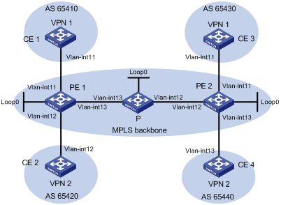
|
设备 |
接口 |
IP地址 |
设备 |
接口 |
IP地址 |
|
CE 1 |
Vlan-int11 |
10.1.1.1/24 |
P |
Loop0 |
2.2.2.9/32 |
|
PE 1 |
Loop0 |
1.1.1.9/32 |
|
Vlan-int12 |
172.2.1.1/24 |
|
|
Vlan-int11 |
10.1.1.2/24 |
|
Vlan-int13 |
172.1.1.2/24 |
|
|
Vlan-int13 |
172.1.1.1/24 |
PE 2 |
Loop0 |
3.3.3.9/32 |
|
|
Vlan-int12 |
10.2.1.2/24 |
|
Vlan-int12 |
172.2.1.2/24 |
|
CE 2 |
Vlan-int12 |
10.2.1.1/24 |
|
Vlan-int11 |
10.3.1.2/24 |
|
CE 3 |
Vlan-int11 |
10.3.1.1/24 |
|
Vlan-int13 |
10.4.1.2/24 |
|
CE 4 |
Vlan-int13 |
10.4.1.1/24 |
|
|
|
(1) 在MPLS骨干网上配置IGP协议,实现骨干网PE和P的互通
# 配置PE 1。
<PE1> system-view
[PE1] interface loopback 0
[PE1-LoopBack0] ip address 1.1.1.9 32
[PE1-LoopBack0] quit
[PE1] interface vlan-interface 13
[PE1-Vlan-interface13] ip address 172.1.1.1 24
[PE1-Vlan-interface13] quit
[PE1] ospf
[PE1-ospf-1] area 0
[PE1-ospf-1-area-0.0.0.0] network 172.1.1.0 0.0.0.255
[PE1-ospf-1-area-0.0.0.0] network 1.1.1.9 0.0.0.0
[PE1-ospf-1-area-0.0.0.0] quit
[PE1-ospf-1] quit
# 配置P。
<P> system-view
[P] interface loopback 0
[P-LoopBack0] ip address 2.2.2.9 32
[P-LoopBack0] quit
[P] interface vlan-interface 13
[P-Vlan-interface13] ip address 172.1.1.2 24
[P-Vlan-interface13] quit
[P] interface vlan-interface 12
[P-Vlan-interface12] ip address 172.2.1.1 24
[P-Vlan-interface12] quit
[P] ospf
[P-ospf-1] area 0
[P-ospf-1-area-0.0.0.0] network 172.1.1.0 0.0.0.255
[P-ospf-1-area-0.0.0.0] network 172.2.1.0 0.0.0.255
[P-ospf-1-area-0.0.0.0] network 2.2.2.9 0.0.0.0
[P-ospf-1-area-0.0.0.0] quit
[P-ospf-1] quit
# 配置PE 2。
<PE2> system-view
[PE2] interface loopback 0
[PE2-LoopBack0] ip address 3.3.3.9 32
[PE2-LoopBack0] quit
[PE2] interface vlan-interface 12
[PE2-Vlan-interface12] ip address 172.2.1.2 24
[PE2-Vlan-interface12] quit
[PE2] ospf
[PE2-ospf-1] area 0
[PE2-ospf-1-area-0.0.0.0] network 172.2.1.0 0.0.0.255
[PE2-ospf-1-area-0.0.0.0] network 3.3.3.9 0.0.0.0
[PE2-ospf-1-area-0.0.0.0] quit
[PE2-ospf-1] quit
配置完成后,PE 1、P、PE 2之间应能建立OSPF邻居,执行display ospf peer命令可以看到邻居达到FULL状态。执行display ip routing-table命令可以看到PE之间学习到对方的Loopback路由。
以PE 1为例:
[PE1] display ip routing-table
Routing Tables: Public
Destinations : 8 Routes : 8
Destination/Mask Proto Pre Cost NextHop Interface
1.1.1.9/32 Direct 0 0 127.0.0.1 InLoop0
2.2.2.9/32 OSPF 10 1 172.1.1.2 Vlan13
3.3.3.9/32 OSPF 10 2 172.1.1.2 Vlan13
127.0.0.0/8 Direct 0 0 127.0.0.1 InLoop0
127.0.0.1/32 Direct 0 0 127.0.0.1 InLoop0
172.1.1.0/24 Direct 0 0 172.1.1.1 Vlan13
172.1.1.1/32 Direct 0 0 127.0.0.1 InLoop0
172.2.1.0/24 OSPF 10 1 172.1.1.2 Vlan13
[PE1] display ospf peer verbose
OSPF Process 1 with Router ID 1.1.1.9
Neighbors
Area 0.0.0.0 interface 172.1.1.1(Vlan-interface13)'s neighbors
Router ID: 172.1.1.2 Address: 172.1.1.2 GR State: Normal
State: Full Mode:Nbr is Master Priority: 1
DR: 172.1.1.1 BDR: 172.1.1.2 MTU: 0
Dead timer due in 38 sec
Neighbor is up for 00:02:44
Authentication Sequence: [ 0 ]
Neighbor state change count: 5
(2) 在MPLS骨干网上配置MPLS基本能力和MPLS LDP,建立LDP LSP
# 配置PE 1。
[PE1] mpls lsr-id 1.1.1.9
[PE1] mpls
[PE1-mpls] quit
[PE1] mpls ldp
[PE1-mpls-ldp] quit
[PE1] interface vlan-interface 13
[PE1-Vlan-interface13] mpls
[PE1-Vlan-interface13] mpls ldp
[PE1-Vlan-interface13] quit
# 配置P。
[P] mpls lsr-id 2.2.2.9
[P] mpls
[P-mpls] quit
[P] mpls ldp
[P-mpls-ldp] quit
[P] interface vlan-interface 13
[P-Vlan-interface13] mpls
[P-Vlan-interface13] mpls ldp
[P-Vlan-interface13] quit
[P] interface vlan-interface 12
[P-Vlan-interface12] mpls
[P-Vlan0interface12] mpls ldp
[P-Vlan-interface12] quit
# 配置PE 2。
[PE2] mpls lsr-id 3.3.3.9
[PE2] mpls
[PE2-mpls] quit
[PE2] mpls ldp
[PE2-mpls-ldp] quit
[PE2] interface vlan-interface 12
[PE2-Vlan-interface12] mpls
[PE2-Vlan-interface12] mpls ldp
[PE2-Vlan-interface12] quit
上述配置完成后,PE 1、P、PE 2之间应能建立LDP会话,执行display mpls ldp session命令可以看到显示结果中Status字段为Operational。执行display mpls ldp lsp命令,可以看到LDP LSP的建立情况。
以PE 1为例:
[PE1] display mpls ldp session
LDP Session(s) in Public Network
Total number of sessions: 1
----------------------------------------------------------------
Peer-ID Status LAM SsnRole FT MD5 KA-Sent/Rcv
---------------------------------------------------------------
2.2.2.9:0 Operational DU Passive Off Off 5/5
---------------------------------------------------------------
LAM : Label Advertisement Mode FT : Fault Tolerance
[PE1] display mpls ldp lsp
LDP LSP Information
------------------------------------------------------------------
SN DestAddress/Mask In/OutLabel Next-Hop In/Out-Interface
------------------------------------------------------------------
1 1.1.1.9/32 3/NULL 127.0.0.1 -------/InLoop0
2 2.2.2.9/32 NULL/3 172.1.1.2 -------/Vlan-interface13
3 3.3.3.9/32 NULL/1024 172.1.1.2 -------/Vlan-interface13
------------------------------------------------------------------
A '*' before an LSP means the LSP is not established
A '*' before a Label means the USCB or DSCB is stale
(3) 在PE设备上配置VPN实例,将CE接入PE
# 配置PE 1。
[PE1] ip vpn-instance vpn1
[PE1-vpn-instance-vpn1] route-distinguisher 100:1
[PE1-vpn-instance-vpn1] vpn-target 111:1
[PE1-vpn-instance-vpn1] quit
[PE1] ip vpn-instance vpn2
[PE1-vpn-instance-vpn2] route-distinguisher 100:2
[PE1-vpn-instance-vpn2] vpn-target 222:2
[PE1-vpn-instance-vpn2] quit
[PE1] interface vlan-interface 11
[PE1-Vlan-interface11] ip binding vpn-instance vpn1
[PE1-Vlan-interface11] ip address 10.1.1.2 24
[PE1-Vlan-interface11] quit
[PE1] interface vlan-interface 12
[PE1-Vlan-interface12] ip binding vpn-instance vpn2
[PE1-Vlan-interface12] ip address 10.2.1.2 24
[PE1-Vlan-interface12] quit
# 配置PE 2。
[PE2] ip vpn-instance vpn1
[PE2-vpn-instance-vpn1] route-distinguisher 200:1
[PE2-vpn-instance-vpn1] vpn-target 111:1
[PE2-vpn-instance-vpn1] quit
[PE2] ip vpn-instance vpn2
[PE2-vpn-instance-vpn2] route-distinguisher 200:2
[PE2-vpn-instance-vpn2] vpn-target 222:2
[PE2-vpn-instance-vpn2] quit
[PE2] interface vlan-interface 11
[PE2-Vlan-interface11] ip binding vpn-instance vpn1
[PE2-Vlan-interface11] ip address 10.3.1.2 24
[PE2-Vlan-interface11] quit
[PE2] interface vlan-interface 13
[PE2-Vlan-interface13] ip binding vpn-instance vpn2
[PE2-Vlan-interface13] ip address 10.4.1.2 24
[PE2-Vlan-interface13] quit
# 配置各CE的接口IP地址,配置过程略。
配置完成后,在PE设备上执行display ip vpn-instance命令可以看到VPN实例的配置情况。各PE能ping通自己接入的CE。
以PE 1和CE 1为例:
[PE1] display ip vpn-instance
Total VPN-Instances configured : 2
VPN-Instance Name RD Create time
vpn1 100:1 2009/01/22 13:02:21
vpn2 100:2 2009/01/22 13:02:40
[PE1] ping -vpn-instance vpn1 10.1.1.1
PING 10.1.1.1: 56 data bytes, press CTRL_C to break
Reply from 10.1.1.1: bytes=56 Sequence=1 ttl=255 time=56 ms
Reply from 10.1.1.1: bytes=56 Sequence=2 ttl=255 time=4 ms
Reply from 10.1.1.1: bytes=56 Sequence=3 ttl=255 time=4 ms
Reply from 10.1.1.1: bytes=56 Sequence=4 ttl=255 time=52 ms
Reply from 10.1.1.1: bytes=56 Sequence=5 ttl=255 time=3 ms
--- 10.1.1.1 ping statistics ---
5 packet(s) transmitted
5 packet(s) received
0.00% packet loss
round-trip min/avg/max = 3/23/56 ms
(4) 在PE与CE之间建立EBGP对等体,引入VPN路由
# 配置CE 1。
<CE1> system-view
[CE1] bgp 65410
[CE1-bgp] peer 10.1.1.2 as-number 100
[CE1-bgp] import-route direct
[CE1-bgp] quit
![]()
另外3个CE设备(CE 2~CE 4)配置与CE 1设备配置类似,配置过程省略。
# 配置PE 1。
[PE1] bgp 100
[PE1-bgp] ipv4-family vpn-instance vpn1
[PE1-bgp-vpn1] peer 10.1.1.1 as-number 65410
[PE1-bgp-vpn1] import-route direct
[PE1-bgp-vpn1] quit
[PE1-bgp] ipv4-family vpn-instance vpn2
[PE1-bgp-vpn2] peer 10.2.1.1 as-number 65420
[PE1-bgp-vpn2] import-route direct
[PE1-bgp-vpn2] quit
[PE1-bgp] quit
![]()
PE 2的配置与PE 1类似,配置过程省略。
配置完成后,在PE设备上执行display bgp vpnv4 vpn-instance peer命令,可以看到PE与CE之间的BGP对等体关系已建立,并达到Established状态。
以PE 1与CE 1的对等体关系为例:
[PE1] display bgp vpnv4 vpn-instance vpn1 peer
BGP local router ID : 1.1.1.9
Local AS number : 100
Total number of peers : 1 Peers in established state : 1
Peer AS MsgRcvd MsgSent OutQ PrefRcv Up/Down State
10.1.1.1 65410 11 9 0 1 00:06:37 Established
(5) 在PE之间建立MP-IBGP对等体
# 配置PE 1。
[PE1] bgp 100
[PE1-bgp] peer 3.3.3.9 as-number 100
[PE1-bgp] peer 3.3.3.9 connect-interface loopback 0
[PE1-bgp] ipv4-family vpnv4
[PE1-bgp-af-vpnv4] peer 3.3.3.9 enable
[PE1-bgp-af-vpnv4] quit
[PE1-bgp] quit
# 配置PE 2。
[PE2] bgp 100
[PE2-bgp] peer 1.1.1.9 as-number 100
[PE2-bgp] peer 1.1.1.9 connect-interface loopback 0
[PE2-bgp] ipv4-family vpnv4
[PE2-bgp-af-vpnv4] peer 1.1.1.9 enable
[PE2-bgp-af-vpnv4] quit
[PE2-bgp] quit
配置完成后,在PE设备上执行display bgp peer或display bgp vpnv4 all peer命令,可以看到PE之间的BGP对等体关系已建立,并达到Established状态。
[PE1] display bgp peer
BGP local router ID : 1.1.1.9
Local AS number : 100
Total number of peers : 1 Peers in established state : 1
Peer AS MsgRcvd MsgSent OutQ PrefRcv Up/Down State
3.3.3.9 100 2 6 0 0 00:00:12 Established
(6) 配置完成后的检验
在PE设备上执行display ip routing-table vpn-instance命令,可以看到去往对端CE的路由。
以PE 1为例:
[PE1] display ip routing-table vpn-instance vpn1
Routing Tables: vpn1
Destinations : 5 Routes : 5
Destination/Mask Proto Pre Cost NextHop Interface
10.1.1.0/24 Direct 0 0 10.1.1.2 Vlan11
10.1.1.2/32 Direct 0 0 127.0.0.1 InLoop0
10.3.1.0/24 BGP 255 0 3.3.3.9 NULL0
127.0.0.0/8 Direct 0 0 127.0.0.1 InLoop0
127.0.0.1/32 Direct 0 0 127.0.0.1 InLoop0
[PE1] display ip routing-table vpn-instance vpn2
Routing Tables: vpn2
Destinations : 5 Routes : 5
Destination/Mask Proto Pre Cost NextHop Interface
10.2.1.0/24 Direct 0 0 10.2.1.2 Vlan12
10.2.1.2/32 Direct 0 0 127.0.0.1 InLoop0
10.4.1.0/24 BGP 255 0 3.3.3.9 NULL0
127.0.0.0/8 Direct 0 0 127.0.0.1 InLoop0
127.0.0.1/32 Direct 0 0 127.0.0.1 InLoop0
同一VPN的CE能够相互Ping通,不同VPN的CE不能相互Ping通。
例如:CE 1能够Ping通CE 3(10.3.1.1),但不能Ping通CE 4(10.4.1.1)。
[CE1] ping 10.3.1.1
PING 10.3.1.1: 56 data bytes, press CTRL_C to break
Reply from 10.3.1.1: bytes=56 Sequence=1 ttl=253 time=72 ms
Reply from 10.3.1.1: bytes=56 Sequence=2 ttl=253 time=34 ms
Reply from 10.3.1.1: bytes=56 Sequence=3 ttl=253 time=50 ms
Reply from 10.3.1.1: bytes=56 Sequence=4 ttl=253 time=50 ms
Reply from 10.3.1.1: bytes=56 Sequence=5 ttl=253 time=34 ms
--- 10.3.1.1 ping statistics ---
5 packet(s) transmitted
5 packet(s) received
0.00% packet loss
round-trip min/avg/max = 34/48/72 ms
[CE1] ping 10.4.1.1
PING 10.4.1.1: 56 data bytes, press CTRL_C to break
Request time out
Request time out
Request time out
Request time out
Request time out
--- 10.4.1.1 ping statistics ---
5 packet(s) transmitted
0 packet(s) received
100.00% packet loss
· CE 1、CE 3属于VPN 1,CE 2、CE 4属于VPN 2;
· VPN 1使用的VPN Target属性为111:1,VPN 2使用的VPN Target属性为222:2。不同VPN用户之间不能互相访问;
· CE与PE之间配置IBGP交换VPN路由信息;
· PE与PE之间配置OSPF实现PE内部的互通、配置MP-IBGP交换VPN路由信息。
图1-20 PE-CE间使用IBGP基本MPLS L3VPN组网图
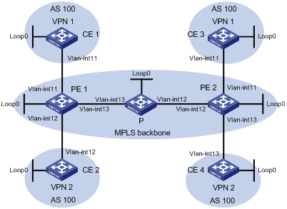
|
设备 |
接口 |
IP地址 |
设备 |
接口 |
IP地址 |
|
PE 1 |
Loop0 |
1.1.1.9/32 |
PE 2 |
Loop0 |
3.3.3.9/32 |
|
|
Vlan-int11 |
10.1.1.2/24 |
|
Vlan-int12 |
172.2.1.2/24 |
|
|
Vlan-int13 |
172.1.1.1/24 |
|
Vlan-int11 |
10.3.1.2/24 |
|
|
Vlan-int12 |
10.2.1.2/24 |
|
Vlan-int13 |
10.4.1.2/24 |
|
CE 1 |
Loop0 |
4.4.4.9/32 |
P |
Loop0 |
2.2.2.9/32 |
|
|
Vlan-int11 |
10.1.1.1/24 |
|
Vlan-int12 |
172.2.1.1/24 |
|
CE 2 |
Loop0 |
5.5.5.9/32 |
|
Vlan-int13 |
172.1.1.2/24 |
|
|
Vlan-int12 |
10.2.1.1/24 |
CE 4 |
Loop0 |
7.7.7.9/32 |
|
CE 3 |
Loop0 |
6.6.6.9/32 |
|
Vlan-int13 |
10.4.1.1/24 |
|
|
Vlan-int11 |
10.3.1.1/24 |
|
|
|
|
|
|
|
|
|
|
(1) 在MPLS骨干网上配置IGP协议,实现骨干网PE和P的互通
# 配置PE 1。
<PE1> system-view
[PE1] interface loopback 0
[PE1-LoopBack0] ip address 1.1.1.9 32
[PE1-LoopBack0] quit
[PE1] interface vlan-interface 13
[PE1-Vlan-interface13] ip address 172.1.1.1 24
[PE1-Vlan-interface13] quit
[PE1] ospf
[PE1-ospf-1] area 0
[PE1-ospf-1-area-0.0.0.0] network 172.1.1.0 0.0.0.255
[PE1-ospf-1-area-0.0.0.0] network 1.1.1.9 0.0.0.0
[PE1-ospf-1-area-0.0.0.0] quit
[PE1-ospf-1] quit
# 配置P。
<P> system-view
[P] interface loopback 0
[P-LoopBack0] ip address 2.2.2.9 32
[P-LoopBack0] quit
[P] interface vlan-interface 13
[P-Vlan-interface13] ip address 172.1.1.2 24
[P-Vlan-interface13] quit
[P] interface vlan-interface 12
[P-Vlan-interface12] ip address 172.2.1.1 24
[P-Vlan-interface12] quit
[P] ospf
[P-ospf-1] area 0
[P-ospf-1-area-0.0.0.0] network 172.1.1.0 0.0.0.255
[P-ospf-1-area-0.0.0.0] network 172.2.1.0 0.0.0.255
[P-ospf-1-area-0.0.0.0] network 2.2.2.9 0.0.0.0
[P-ospf-1-area-0.0.0.0] quit
[P-ospf-1] quit
# 配置PE 2。
<PE2> system-view
[PE2] interface loopback 0
[PE2-LoopBack0] ip address 3.3.3.9 32
[PE2-LoopBack0] quit
[PE2] interface vlan-interface 12
[PE2-Vlan-interface12] ip address 172.2.1.2 24
[PE2-Vlan-interface12] quit
[PE2] ospf
[PE2-ospf-1] area 0
[PE2-ospf-1-area-0.0.0.0] network 172.2.1.0 0.0.0.255
[PE2-ospf-1-area-0.0.0.0] network 3.3.3.9 0.0.0.0
[PE2-ospf-1-area-0.0.0.0] quit
[PE2-ospf-1] quit
配置完成后,PE 1、P、PE 2之间应能建立OSPF邻居,执行display ospf peer命令可以看到邻居达到FULL状态。执行display ip routing-table命令可以看到PE之间学习到对方的Loopback路由。
以PE 1为例:
[PE1] display ip routing-table
Routing Tables: Public
Destinations : 8 Routes : 8
Destination/Mask Proto Pre Cost NextHop Interface
1.1.1.9/32 Direct 0 0 127.0.0.1 InLoop0
2.2.2.9/32 OSPF 10 1 172.1.1.2 Vlan13
3.3.3.9/32 OSPF 10 2 172.1.1.2 Vlan13
127.0.0.0/8 Direct 0 0 127.0.0.1 InLoop0
127.0.0.1/32 Direct 0 0 127.0.0.1 InLoop0
172.1.1.0/24 Direct 0 0 172.1.1.1 Vlan13
172.1.1.1/32 Direct 0 0 127.0.0.1 InLoop0
172.2.1.0/24 OSPF 10 1 172.1.1.2 Vlan13
[PE1] display ospf peer verbose
OSPF Process 1 with Router ID 1.1.1.9
Neighbors
Area 0.0.0.0 interface 172.1.1.1(Vlan-interface13)'s neighbors
Router ID: 172.1.1.2 Address: 172.1.1.2 GR State: Normal
State: Full Mode:Nbr is Master Priority: 1
DR: 172.1.1.1 BDR: 172.1.1.2 MTU: 0
Dead timer due in 38 sec
Neighbor is up for 00:02:44
Authentication Sequence: [ 0 ]
Neighbor state change count: 5
(2) 在MPLS骨干网上配置MPLS基本能力和MPLS LDP,建立LDP LSP
# 配置PE 1。
[PE1] mpls lsr-id 1.1.1.9
[PE1] mpls
[PE1-mpls] quit
[PE1] mpls ldp
[PE1-mpls-ldp] quit
[PE1] interface vlan-interface 13
[PE1-Vlan-interface13] mpls
[PE1-Vlan-interface13] mpls ldp
[PE1-Vlan-interface13] quit
# 配置P。
[P] mpls lsr-id 2.2.2.9
[P] mpls
[P-mpls] quit
[P] mpls ldp
[P-mpls-ldp] quit
[P] interface vlan-interface 13
[P-Vlan-interface13] mpls
[P-Vlan-interface13] mpls ldp
[P-Vlan-interface13] quit
[P] interface vlan-interface 12
[P-Vlan-interface12] mpls
[P-Vlan0interface12] mpls ldp
[P-Vlan-interface12] quit
# 配置PE 2。
[PE2] mpls lsr-id 3.3.3.9
[PE2] mpls
[PE2-mpls] quit
[PE2] mpls ldp
[PE2-mpls-ldp] quit
[PE2] interface vlan-interface 12
[PE2-Vlan-interface12] mpls
[PE2-Vlan-interface12] mpls ldp
[PE2-Vlan-interface12] quit
上述配置完成后,PE 1、P、PE 2之间应能建立LDP会话,执行display mpls ldp session命令可以看到显示结果中Status字段为Operational。执行display mpls ldp lsp命令,可以看到LDP LSP的建立情况。
以PE 1为例:
[PE1] display mpls ldp session
LDP Session(s) in Public Network
Total number of sessions: 1
----------------------------------------------------------------
Peer-ID Status LAM SsnRole FT MD5 KA-Sent/Rcv
---------------------------------------------------------------
2.2.2.9:0 Operational DU Passive Off Off 5/5
---------------------------------------------------------------
LAM : Label Advertisement Mode FT : Fault Tolerance
[PE1] display mpls ldp lsp
LDP LSP Information
------------------------------------------------------------------
SN DestAddress/Mask In/OutLabel Next-Hop In/Out-Interface
------------------------------------------------------------------
1 1.1.1.9/32 3/NULL 127.0.0.1 -------/InLoop0
2 2.2.2.9/32 NULL/3 172.1.1.2 -------/Vlan-interface13
3 3.3.3.9/32 NULL/1024 172.1.1.2 -------/Vlan-interface13
------------------------------------------------------------------
A '*' before an LSP means the LSP is not established
A '*' before a Label means the USCB or DSCB is stale
(3) 在PE设备上配置VPN实例,将CE接入PE
# 配置PE 1。
[PE1] ip vpn-instance vpn1
[PE1-vpn-instance-vpn1] route-distinguisher 100:1
[PE1-vpn-instance-vpn1] vpn-target 111:1
[PE1-vpn-instance-vpn1] quit
[PE1] ip vpn-instance vpn2
[PE1-vpn-instance-vpn2] route-distinguisher 100:2
[PE1-vpn-instance-vpn2] vpn-target 222:2
[PE1-vpn-instance-vpn2] quit
[PE1] interface vlan-interface 11
[PE1-Vlan-interface11] ip binding vpn-instance vpn1
[PE1-Vlan-interface11] ip address 10.1.1.2 24
[PE1-Vlan-interface11] quit
[PE1] interface vlan-interface 12
[PE1-Vlan-interface12] ip binding vpn-instance vpn2
[PE1-Vlan-interface12] ip address 10.2.1.2 24
[PE1-Vlan-interface12] quit
# 配置PE 2。
[PE2] ip vpn-instance vpn1
[PE2-vpn-instance-vpn1] route-distinguisher 200:1
[PE2-vpn-instance-vpn1] vpn-target 111:1
[PE2-vpn-instance-vpn1] quit
[PE2] ip vpn-instance vpn2
[PE2-vpn-instance-vpn2] route-distinguisher 200:2
[PE2-vpn-instance-vpn2] vpn-target 222:2
[PE2-vpn-instance-vpn2] quit
[PE2] interface vlan-interface 11
[PE2-Vlan-interface11] ip binding vpn-instance vpn1
[PE2-Vlan-interface11] ip address 10.3.1.2 24
[PE2-Vlan-interface11] quit
[PE2] interface vlan-interface 13
[PE2-Vlan-interface13] ip binding vpn-instance vpn2
[PE2-Vlan-interface13] ip address 10.4.1.2 24
[PE2-Vlan-interface13] quit
# 配置各CE的接口IP地址,配置过程略。
配置完成后,在PE设备上执行display ip vpn-instance命令可以看到VPN实例的配置情况。各PE能ping通自己接入的CE。
以PE 1和CE 1为例:
[PE1] display ip vpn-instance
Total VPN-Instances configured : 2
VPN-Instance Name RD Create time
vpn1 100:1 2009/01/22 13:02:21
vpn2 100:2 2009/01/22 13:02:40
[PE1] ping -vpn-instance vpn1 10.1.1.1
PING 10.1.1.1: 56 data bytes, press CTRL_C to break
Reply from 10.1.1.1: bytes=56 Sequence=1 ttl=255 time=56 ms
Reply from 10.1.1.1: bytes=56 Sequence=2 ttl=255 time=4 ms
Reply from 10.1.1.1: bytes=56 Sequence=3 ttl=255 time=4 ms
Reply from 10.1.1.1: bytes=56 Sequence=4 ttl=255 time=52 ms
Reply from 10.1.1.1: bytes=56 Sequence=5 ttl=255 time=3 ms
--- 10.1.1.1 ping statistics ---
5 packet(s) transmitted
5 packet(s) received
0.00% packet loss
round-trip min/avg/max = 3/23/56 ms
(4) 在PE与CE之间建立IBGP对等体,引入VPN路由,并配置路由策略修改路由的下一跳
# 在CE 1上配置IBGP对等体,并对从PE 1接收的路由应用路由策略,将路由下一跳修改为PE 1的地址。
<CE1> system-view
[CE1] route-policy ce-ibgp permit node 0
[CE1-route-policy] apply ip-address next-hop 10.1.1.2
[CE1-route-policy] quit
[CE1] bgp 100
[CE1-bgp] peer 10.1.1.2 as-number 100
[CE1-bgp] peer 10.1.1.2 route-policy ce-ibgp import
[CE1-bgp] import-route direct
[CE1-bgp] quit
![]()
另外3个CE设备(CE 2~CE 4)配置与CE 1设备配置类似,配置过程省略。
# 在PE 1上配置IBGP对等体,并配置PE 1作为路由反射器反射路由。
[PE1] bgp 100
[PE1-bgp] ipv4-family vpn-instance vpn1
[PE1-bgp-vpn1] peer 10.1.1.1 as-number 100
[PE1-bgp-vpn1] peer 10.1.1.1 reflect-client
[PE1-bgp-vpn1] import-route direct
[PE1-bgp-vpn1] quit
[PE1-bgp] ipv4-family vpn-instance vpn2
[PE1-bgp-vpn2] peer 10.2.1.1 as-number 100
[PE1-bgp-vpn2] peer 10.2.1.1 reflect-client
[PE1-bgp-vpn2] import-route direct
[PE1-bgp-vpn2] quit
[PE1-bgp] quit
![]()
PE 2的配置与PE 1类似,配置过程省略。
配置完成后,在PE设备上执行display bgp vpnv4 vpn-instance peer命令,可以看到PE与CE之间的BGP对等体关系已建立,并达到Established状态。
以PE 1与CE 1的对等体关系为例:
[PE1] display bgp vpnv4 vpn-instance vpn1 peer
BGP local router ID : 1.1.1.9
Local AS number : 100
Total number of peers : 1 Peers in established state : 1
Peer AS MsgRcvd MsgSent OutQ PrefRcv Up/Down State
10.1.1.1 100 26 21 0 2 00:11:08 Established
(5) 在PE之间建立MP-IBGP对等体
# 在PE 1上配置MP-IBGP对等体,并对从PE 2接收的路由应用路由策略,将路由下一跳修改为PE 2的环回接口地址。
[PE1] route-policy pe-ibgp permit node 0
[PE1-route-policy] apply ip-address next-hop 3.3.3.9
[PE1-route-policy] quit
[PE1] bgp 100
[PE1-bgp] peer 3.3.3.9 as-number 100
[PE1-bgp] peer 3.3.3.9 connect-interface loopback 0
[PE1-bgp] ipv4-family vpnv4
[PE1-bgp-af-vpnv4] peer 3.3.3.9 route-policy pe-ibgp import
[PE1-bgp-af-vpnv4] peer 3.3.3.9 enable
[PE1-bgp-af-vpnv4] quit
[PE1-bgp] quit
# 在PE 2上配置MP-IBGP对等体,并对从PE 1接收的路由应用路由策略,将路由下一跳修改为PE 1的环回接口地址。
[PE2] route-policy pe-ibgp permit node 0
[PE2-route-policy] apply ip-address next-hop 1.1.1.9
[PE2-route-policy] quit
[PE2] bgp 100
[PE2-bgp] peer 1.1.1.9 as-number 100
[PE2-bgp] peer 1.1.1.9 connect-interface loopback 0
[PE2-bgp] ipv4-family vpnv4
[PE2-bgp-af-vpnv4] peer 1.1.1.9 route-policy pe-ibgp import
[PE2-bgp-af-vpnv4] peer 1.1.1.9 enable
[PE2-bgp-af-vpnv4] quit
[PE2-bgp] quit
配置完成后,在PE设备上执行display bgp peer或display bgp vpnv4 all peer命令,可以看到PE之间的BGP对等体关系已建立,并达到Established状态。
[PE1] display bgp peer
BGP local router ID : 1.1.1.9
Local AS number : 100
Total number of peers : 1 Peers in established state : 1
Peer AS MsgRcvd MsgSent OutQ PrefRcv Up/Down State
3.3.3.9 100 4 8 0 0 00:00:09 Established
(6) 配置完成后的检验
在PE设备上执行display ip routing-table vpn-instance命令,可以看到去往对端CE的路由。
以PE 1为例:
[PE1] display ip routing-table vpn-instance vpn1
Routing Tables: vpn1
Destinations : 7 Routes : 7
Destination/Mask Proto Pre Cost NextHop Interface
4.4.4.9/32 BGP 255 0 10.1.1.1 Vlan11
6.6.6.9/32 BGP 255 0 3.3.3.9 NULL0
10.1.1.0/24 Direct 0 0 10.1.1.2 Vlan11
10.1.1.2/32 Direct 0 0 127.0.0.1 InLoop0
10.3.1.0/24 BGP 255 0 3.3.3.9 NULL0
127.0.0.0/8 Direct 0 0 127.0.0.1 InLoop0
127.0.0.1/32 Direct 0 0 127.0.0.1 InLoop0
[PE1] display ip routing-table vpn-instance vpn2
Routing Tables: vpn2
Destinations : 5 Routes : 5
Destination/Mask Proto Pre Cost NextHop Interface
5.5.5.9/32 BGP 255 0 10.2.1.1 Vlan12
7.7.7.9/32 BGP 255 0 3.3.3.9 NULL0
10.2.1.0/24 Direct 0 0 10.2.1.2 Vlan12
10.2.1.2/32 Direct 0 0 127.0.0.1 InLoop0
10.4.1.0/24 BGP 255 0 3.3.3.9 NULL0
127.0.0.0/8 Direct 0 0 127.0.0.1 InLoop0
127.0.0.1/32 Direct 0 0 127.0.0.1 InLoop0
同一VPN的CE能够相互Ping通,不同VPN的CE不能相互Ping通。
例如:CE 1能够Ping通CE 3(6.6.6.9),但不能Ping通CE 4(7.7.7.9)。
[CE1] ping 6.6.6.9
PING 6.6.6.9: 56 data bytes, press CTRL_C to break
Reply from 6.6.6.9: bytes=56 Sequence=1 ttl=253 time=72 ms
Reply from 6.6.6.9: bytes=56 Sequence=2 ttl=253 time=34 ms
Reply from 6.6.6.9: bytes=56 Sequence=3 ttl=253 time=50 ms
Reply from 6.6.6.9: bytes=56 Sequence=4 ttl=253 time=50 ms
Reply from 6.6.6.9: bytes=56 Sequence=5 ttl=253 time=34 ms
--- 6.6.6.9 ping statistics ---
5 packet(s) transmitted
5 packet(s) received
0.00% packet loss
round-trip min/avg/max = 34/48/72 ms
[CE1] ping 7.7.7.9
PING 7.7.7.9: 56 data bytes, press CTRL_C to break
Request time out
Request time out
Request time out
Request time out
Request time out
--- 7.7.7.9 ping statistics ---
5 packet(s) transmitted
0 packet(s) received
100.00% packet loss
· Spoke-CE之间不能直接通信,只能通过Hub-CE转发Spoke-CE之间的流量。
· Spoke-CE与Spoke-PE之间、Hub-CE与Hub-PE之间配置EBGP交换VPN路由信息。
· Spoke-PE与Hub-PE之间配置OSPF实现PE内部的互通、配置MP-IBGP交换VPN路由信息。
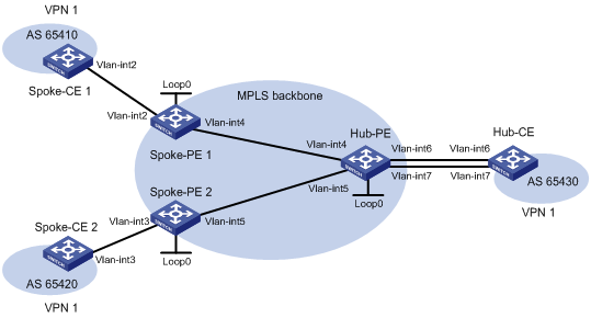
|
设备 |
接口 |
IP地址 |
设备 |
接口 |
IP地址 |
|
Spoke-CE 1 |
Vlan-int2 |
10.1.1.1/24 |
Hub-CE |
Vlan-int6 |
10.3.1.1/24 |
|
Spoke-PE 1 |
Loop0 |
1.1.1.9/32 |
|
Vlan-int7 |
10.4.1.1/24 |
|
|
Vlan-int2 |
10.1.1.2/24 |
Hub-PE |
Loop0 |
2.2.2.9/32 |
|
|
Vlan-int4 |
172.1.1.1/24 |
|
Vlan-int4 |
172.1.1.2/24 |
|
Spoke-CE 2 |
Vlan-int3 |
10.2.1.1/24 |
|
Vlan-int5 |
172.2.1.2/24 |
|
Spoke-PE 2 |
Loop0 |
3.3.3.9/32 |
|
Vlan-int6 |
10.3.1.2/24 |
|
|
Vlan-int3 |
10.2.1.2/24 |
|
Vlan-int7 |
10.4.1.2/24 |
|
|
Vlan-int5 |
172.2.1.1/24 |
|
|
|
(1) 在MPLS骨干网上配置IGP协议,实现骨干网Spoke-PE、Hub-PE之间的互通
# 配置Spoke-PE 1。
<Spoke-PE1> system-view
[Spoke-PE1] interface loopback 0
[Spoke-PE1-LoopBack0] ip address 1.1.1.9 32
[Spoke-PE1-LoopBack0] quit
[Spoke-PE1] interface vlan-interface 4
[Spoke-PE1-Vlan-interface4] ip address 172.1.1.1 24
[Spoke-PE1-Vlan-interface4] quit
[Spoke-PE1] ospf
[Spoke-PE1-ospf-1] area 0
[Spoke-PE1-ospf-1-area-0.0.0.0] network 172.1.1.0 0.0.0.255
[Spoke-PE1-ospf-1-area-0.0.0.0] network 1.1.1.9 0.0.0.0
[Spoke-PE1-ospf-1-area-0.0.0.0] quit
[Spoke-PE1-ospf-1] quit
# 配置Spoke-PE 2。
<Spoke-PE2> system-view
[Spoke-PE2] interface loopback 0
[Spoke-PE2-LoopBack0] ip address 3.3.3.9 32
[Spoke-PE2-LoopBack0] quit
[Spoke-PE2] interface vlan-interface 5
[Spoke-PE2-Vlan-interface5] ip address 172.2.1.1 24
[Spoke-PE2-Vlan-interface5] quit
[Spoke-PE2] ospf
[Spoke-PE2-ospf-1] area 0
[Spoke-PE2-ospf-1-area-0.0.0.0] network 172.2.1.0 0.0.0.255
[Spoke-PE2-ospf-1-area-0.0.0.0] network 3.3.3.9 0.0.0.0
[Spoke-PE2-ospf-1-area-0.0.0.0] quit
[Spoke-PE2-ospf-1] quit
# 配置Hub-PE。
<Hub-PE> system-view
[Hub-PE] interface loopback 0
[Hub-PE-LoopBack0] ip address 2.2.2.9 32
[Hub-PE-LoopBack0] quit
[Hub-PE] interface vlan-interface 4
[Hub-PE-Vlan-interface4] ip address 172.1.1.2 24
[Hub-PE-Vlan-interface4] quit
[Hub-PE] interface vlan-interface 5
[Hub-PE-Vlan-interface5] ip address 172.2.1.2 24
[Hub-PE-Vlan-interface5] quit
[Hub-PE] ospf
[Hub-PE-ospf-1] area 0
[Hub-PE-ospf-1-area-0.0.0.0] network 172.1.1.0 0.0.0.255
[Hub-PE-ospf-1-area-0.0.0.0] network 172.2.1.0 0.0.0.255
[Hub-PE-ospf-1-area-0.0.0.0] network 2.2.2.9 0.0.0.0
[Hub-PE-ospf-1-area-0.0.0.0] quit
[Hub-PE-ospf-1] quit
配置完成后,Spoke-PE 1、Spoke-PE 2、Hub-PE之间应能建立OSPF邻居,执行display ospf peer命令可以看到邻居达到FULL状态。执行display ip routing-table命令可以看到PE之间学习到对方的Loopback路由。
以Spoke-PE 1为例:
[Spoke-PE1] display ip routing-table
Routing Tables: Public
Destinations : 10 Routes : 10
Destination/Mask Proto Pre Cost NextHop Interface
1.1.1.9/32 Direct 0 0 127.0.0.1 InLoop0
2.2.2.9/32 OSPF 10 1 172.1.1.2 Vlan4
3.3.3.9/32 OSPF 10 2 172.1.1.2 Vlan4
10.1.1.0/24 Direct 0 0 10.1.1.2 Vlan2
10.1.1.2/32 Direct 0 0 127.0.0.1 InLoop0
127.0.0.0/8 Direct 0 0 127.0.0.1 InLoop0
127.0.0.1/32 Direct 0 0 127.0.0.1 InLoop0
172.1.1.0/24 Direct 0 0 172.1.1.1 Vlan4
172.1.1.1/32 Direct 0 0 127.0.0.1 InLoop0
172.2.1.0/24 OSPF 10 1 172.1.1.2 Vlan4
[Spoke-PE1] display ospf peer verbose
OSPF Process 1 with Router ID 1.1.1.9
Neighbors
Area 0.0.0.0 interface 172.1.1.1(Vlan-interface4)'s neighbors
Router ID: 2.2.2.9 Address: 172.1.1.2 GR State: Normal
State: Full Mode:Nbr is Master Priority: 1
DR: 172.1.1.1 BDR: 172.1.1.2 MTU: 0
Dead timer due in 38 sec
Neighbor is up for 00:02:44
Authentication Sequence: [ 0 ]
Neighbor state change count: 5
(2) 在MPLS骨干网上配置MPLS基本能力和MPLS LDP,建立LDP LSP
# 配置Spoke-PE 1。
[Spoke-PE1] mpls lsr-id 1.1.1.9
[Spoke-PE1] mpls
[Spoke-PE1-mpls] quit
[Spoke-PE1] mpls ldp
[Spoke-PE1-mpls-ldp] quit
[Spoke-PE1] interface vlan-interface 4
[Spoke-PE1-Vlan-interface4] mpls
[Spoke-PE1-Vlan-interface4] mpls ldp
[Spoke-PE1-Vlan-interface4] quit
# 配置Spoke-PE 2。
[Spoke-PE2] mpls lsr-id 3.3.3.9
[Spoke-PE2] mpls
[Spoke-PE2-mpls] quit
[Spoke-PE2] mpls ldp
[Spoke-PE2-mpls-ldp] quit
[Spoke-PE2] interface vlan-interface 5
[Spoke-PE2-Vlan-interface5] mpls
[Spoke-PE2-Vlan-interface5] mpls ldp
[Spoke-PE2-Vlan-interface5] quit
# 配置Hub-PE。
[Hub-PE] mpls lsr-id 2.2.2.9
[Hub-PE] mpls
[Hub-PE-mpls] quit
[Hub-PE] mpls ldp
[Hub-PE-mpls-ldp] quit
[Hub-PE] interface vlan-interface 4
[Hub-PE-Vlan-interface4] mpls
[Hub-PE-Vlan-interface4] mpls ldp
[Hub-PE-Vlan-interface4] quit
[Hub-PE] interface vlan-interface 5
[Hub-PE-Vlan-interface5] mpls
[Hub-PE-Vlan-interface5] mpls ldp
[Hub-PE-Vlan-interface5] quit
上述配置完成后,Spoke-PE 1、Spoke-PE 2、Hub-PE之间应能建立LDP会话,执行display mpls ldp session命令可以看到显示结果中Status字段为Operational。执行display mpls ldp lsp命令,可以看到LDP LSP的建立情况。
以Spoke-PE 1为例:
[Spoke-PE1] display mpls ldp session
LDP Session(s) in Public Network
Total number of sessions: 1
----------------------------------------------------------------
Peer-ID Status LAM SsnRole FT MD5 KA-Sent/Rcv
---------------------------------------------------------------
2.2.2.9:0 Operational DU Passive Off Off 5/5
---------------------------------------------------------------
LAM : Label Advertisement Mode FT : Fault Tolerance
[Spoke-PE1] display mpls ldp lsp
LDP LSP Information
------------------------------------------------------------------
SN DestAddress/Mask In/OutLabel Next-Hop In/Out-Interface
------------------------------------------------------------------
1 1.1.1.9/32 3/NULL 127.0.0.1 -------/InLoop0
2 2.2.2.9/32 NULL/3 172.1.1.2 -------/Vlan-interface4
3 3.3.3.9/32 NULL/1024 172.1.1.2 -------/Vlan-interface4
------------------------------------------------------------------
A '*' before an LSP means the LSP is not established
A '*' before a Label means the USCB or DSCB is stale
(3) 在Spoke-PE和Hub-PE设备上配置VPN实例,将CE接入PE
# 配置Spoke-PE 1。
[Spoke-PE1] ip vpn-instance vpn1
[Spoke-PE1-vpn-instance-vpn1] route-distinguisher 100:1
[Spoke-PE1-vpn-instance-vpn1] vpn-target 111:1 import-extcommunity
[Spoke-PE1-vpn-instance-vpn1] vpn-target 222:2 export-extcommunity
[Spoke-PE1-vpn-instance-vpn1] quit
[Spoke-PE1] interface vlan-interface 2
[Spoke-PE1-Vlan-interface2] ip binding vpn-instance vpn1
[Spoke-PE1-Vlan-interface2] ip address 10.1.1.2 24
[Spoke-PE1-Vlan-interface2] quit
# 配置Spoke-PE 2。
[Spoke-PE2] ip vpn-instance vpn1
[Spoke-PE2-vpn-instance-vpn1] route-distinguisher 100:2
[Spoke-PE2-vpn-instance-vpn1] vpn-target 111:1 import-extcommunity
[Spoke-PE2-vpn-instance-vpn1] vpn-target 222:2 export-extcommunity
[Spoke-PE2-vpn-instance-vpn1] quit
[Spoke-PE2] interface vlan-interface 3
[Spoke-PE2-Vlan-interface3] ip binding vpn-instance vpn1
[Spoke-PE2-Vlan-interface3] ip address 10.2.1.2 24
[Spoke-PE2-Vlan-interface3] quit
# 配置Hub-PE。
[Hub-PE] ip vpn-instance vpn1-in
[Hub-PE-vpn-instance-vpn1-in] route-distinguisher 100:3
[Hub-PE-vpn-instance-vpn1-in] vpn-target 222:2 import-extcommunity
[Hub-PE-vpn-instance-vpn1-in] quit
[Hub-PE] ip vpn-instance vpn1-out
[Hub-PE-vpn-instance-vpn1-out] route-distinguisher 100:4
[Hub-PE-vpn-instance-vpn1-out] vpn-target 111:1 export-extcommunity
[Hub-PE-vpn-instance-vpn1-out] quit
[Hub-PE] interface vlan-interface 6
[Hub-PE-Vlan-interface6] ip binding vpn-instance vpn1-in
[Hub-PE-Vlan-interface6] ip address 10.3.1.2 24
[Hub-PE-Vlan-interface6] quit
[Hub-PE] interface vlan-interface 7
[Hub-PE-Vlan-interface7] ip binding vpn-instance vpn1-out
[Hub-PE-Vlan-interface7] ip address 10.4.1.2 24
[Hub-PE-Vlan-interface7] quit
# 按图1-21配置各CE的接口IP地址,配置过程略。
配置完成后,在PE设备上执行display ip vpn-instance命令可以看到VPN实例的配置情况。各PE能ping通自己接入的CE。
以Spoke-PE 1和Spoke-CE 1为例:
[Spoke-PE1] display ip vpn-instance
Total VPN-Instances configured : 1
VPN-Instance Name RD Create time
vpn1 100:1 2009/04/08 10:55:07
[Spoke-PE1] ping -vpn-instance vpn1 10.1.1.1
PING 10.1.1.1: 56 data bytes, press CTRL_C to break
Reply from 10.1.1.1: bytes=56 Sequence=1 ttl=255 time=56 ms
Reply from 10.1.1.1: bytes=56 Sequence=2 ttl=255 time=4 ms
Reply from 10.1.1.1: bytes=56 Sequence=3 ttl=255 time=4 ms
Reply from 10.1.1.1: bytes=56 Sequence=4 ttl=255 time=52 ms
Reply from 10.1.1.1: bytes=56 Sequence=5 ttl=255 time=3 ms
--- 10.1.1.1 ping statistics ---
5 packet(s) transmitted
5 packet(s) received
0.00% packet loss
round-trip min/avg/max = 3/23/56 ms
(4) 在PE与CE之间建立EBGP对等体,引入VPN路由
# 配置Spoke-CE 1。
<Spoke-CE1> system-view
[Spoke-CE1] bgp 65410
[Spoke-CE1-bgp] peer 10.1.1.2 as-number 100
[Spoke-CE1-bgp] import-route direct
[Spoke-CE1-bgp] quit
# 配置Spoke-CE 2。
<Spoke-CE2> system-view
[Spoke-CE2] bgp 65420
[Spoke-CE2-bgp] peer 10.2.1.2 as-number 100
[Spoke-CE2-bgp] import-route direct
[Spoke-CE2-bgp] quit
# 配置Hub-CE。
<Hub-CE> system-view
[Hub-CE] bgp 65430
[Hub-CE-bgp] peer 10.3.1.2 as-number 100
[Hub-CE-bgp] peer 10.4.1.2 as-number 100
[Hub-CE-bgp] import-route direct
[Hub-CE-bgp] quit
# 配置Spoke-PE 1。
[Spoke-PE1] bgp 100
[Spoke-PE1-bgp] ipv4-family vpn-instance vpn1
[Spoke-PE1-bgp-vpn1] peer 10.1.1.1 as-number 65410
[Spoke-PE1-bgp-vpn1] import-route direct
[Spoke-PE1-bgp-vpn1] quit
[Spoke-PE1-bgp] quit
# 配置Spoke-PE 2。
[Spoke-PE2] bgp 100
[Spoke-PE2-bgp] ipv4-family vpn-instance vpn1
[Spoke-PE2-bgp-vpn1] peer 10.2.1.1 as-number 65420
[Spoke-PE2-bgp-vpn1] import-route direct
[Spoke-PE2-bgp-vpn1] quit
[Spoke-PE2-bgp] quit
# 配置Hub-PE。
[Hub-PE] bgp 100
[Hub-PE-bgp] ipv4-family vpn-instance vpn1-in
[Hub-PE-bgp-vpn1-in] peer 10.3.1.1 as-number 65430
[Hub-PE-bgp-vpn1-in] import-route direct
[Hub-PE-bgp-vpn1-in] quit
[Hub-PE-bgp] ipv4-family vpn-instance vpn1-out
[Hub-PE-bgp-vpn1-out] peer 10.4.1.1 as-number 65430
[Hub-PE-bgp-vpn1-out] peer 10.4.1.1 allow-as-loop
[Hub-PE-bgp-vpn1-out] import-route direct
[Hub-PE-bgp-vpn1-out] quit
[Hub-PE-bgp] quit
配置完成后,在PE设备上执行display bgp vpnv4 vpn-instance peer命令,可以看到PE与CE之间的BGP对等体关系已建立,并达到Established状态。
以Spoke-PE 1与Spoke-CE 1的对等体关系为例:
[Spoke-PE1] display bgp vpnv4 vpn-instance vpn1 peer
BGP local router ID : 1.1.1.9
Local AS number : 100
Total number of peers : 1 Peers in established state : 1
Peer AS MsgRcvd MsgSent OutQ PrefRcv Up/Down State
10.1.1.1 65410 6 7 0 2 00:03:16 Established
(5) 在Spoke-PE和Hub-PE之间建立MP-IBGP对等体
# 配置Spoke-PE 1。
[Spoke-PE1] bgp 100
[Spoke-PE1-bgp] peer 2.2.2.9 as-number 100
[Spoke-PE1-bgp] peer 2.2.2.9 connect-interface loopback 0
[Spoke-PE1-bgp] ipv4-family vpnv4
[Spoke-PE1-bgp-af-vpnv4] peer 2.2.2.9 enable
[Spoke-PE1-bgp-af-vpnv4] quit
[Spoke-PE1-bgp] quit
# 配置Spoke-PE 2。
[Spoke-PE2] bgp 100
[Spoke-PE2-bgp] peer 2.2.2.9 as-number 100
[Spoke-PE2-bgp] peer 2.2.2.9 connect-interface loopback 0
[Spoke-PE2-bgp] ipv4-family vpnv4
[Spoke-PE2-bgp-af-vpnv4] peer 2.2.2.9 enable
[Spoke-PE2-bgp-af-vpnv4] quit
[Spoke-PE2-bgp] quit
# 配置Hub-PE。
[Hub-PE] bgp 100
[Hub-PE-bgp] peer 1.1.1.9 as-number 100
[Hub-PE-bgp] peer 1.1.1.9 connect-interface loopback 0
[Hub-PE-bgp] peer 3.3.3.9 as-number 100
[Hub-PE-bgp] peer 3.3.3.9 connect-interface loopback 0
[Hub-PE-bgp] ipv4-family vpnv4
[Hub-PE-bgp-af-vpnv4] peer 1.1.1.9 enable
[Hub-PE-bgp-af-vpnv4] peer 3.3.3.9 enable
[Hub-PE-bgp-af-vpnv4] quit
[Hub-PE-bgp] quit
配置完成后,在PE设备上执行display bgp peer或display bgp vpnv4 all peer命令,可以看到PE之间的BGP对等体关系已建立,并达到Established状态。
[Spoke-PE1] display bgp peer
BGP local router ID : 1.1.1.9
Local AS number : 100
Total number of peers : 1 Peers in established state : 1
Peer AS MsgRcvd MsgSent OutQ PrefRcv Up/Down State
2.2.2.9 100 6 5 0 0 00:00:32 Established
(6) 配置完成后的检验
# 在PE设备上执行display ip routing-table vpn-instance命令,可以看到去往各个CE的路由,且Spoke-PE上到达对端Spoke-CE的路由指向Hub-PE。以Spoke-PE 1为例:
[Spoke-PE1] display ip routing-table vpn-instance vpn1
Routing Tables: vpn1
Destinations : 8 Routes : 8
Destination/Mask Proto Pre Cost NextHop Interface
10.0.0.0/24 BGP 255 0 2.2.2.9 NULL0
10.1.1.0/24 Direct 0 0 10.1.1.2 Vlan2
10.1.1.2/32 Direct 0 0 127.0.0.1 InLoop0
10.2.1.0/24 BGP 255 0 2.2.2.9 NULL0
10.3.1.0/24 BGP 255 0 2.2.2.9 NULL0
10.4.1.0/24 BGP 255 0 2.2.2.9 NULL0
127.0.0.0/8 Direct 0 0 127.0.0.1 InLoop0
127.0.0.1/32 Direct 0 0 127.0.0.1 InLoop0
# Spoke-CE 1和Spoke-CE 2之间可以ping通。从TTL值可以推算出Spoke-CE 1到Spoke-CE 2经过6跳(255-250+1),即Spoke-CE 1和Spoke-CE 2之间的流量需要通过Hub-CE转发。以Spoke-CE 1为例:
[Spoke-CE1] ping 10.2.1.1
PING 10.2.1.1: 56 data bytes, press CTRL_C to break
Reply from 10.2.1.1: bytes=56 Sequence=1 ttl=250 time=3 ms
Reply from 10.2.1.1: bytes=56 Sequence=2 ttl=250 time=3 ms
Reply from 10.2.1.1: bytes=56 Sequence=3 ttl=250 time=2 ms
Reply from 10.2.1.1: bytes=56 Sequence=4 ttl=250 time=2 ms
Reply from 10.2.1.1: bytes=56 Sequence=5 ttl=250 time=2 ms
--- 10.2.1.1 ping statistics ---
5 packet(s) transmitted
5 packet(s) received
0.00% packet loss
round-trip min/avg/max = 2/2/3 ms
· CE 1和CE 2属于同一个VPN。
· CE 1通过AS100的PE 1接入,CE 2通过AS200的PE 2接入。
· 采用OptionA方式实现跨域的MPLS L3VPN,即,采用VRF-to-VRF方式管理VPN路由。
· 同一个AS内部的MPLS骨干网使用OSPF作为IGP。
图1-22 配置跨域VPN-OptionA方式组网图
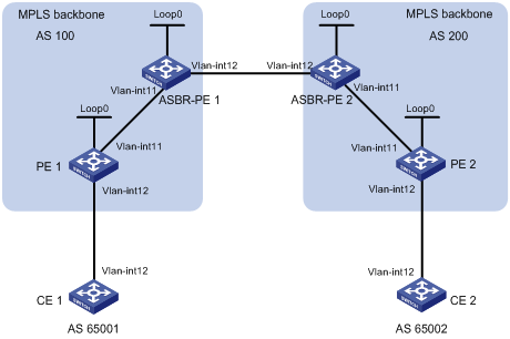
|
设备 |
接口 |
IP地址 |
设备 |
接口 |
IP地址 |
|
CE 1 |
Vlan-int12 |
10.1.1.1/24 |
CE 2 |
Vlan-int12 |
10.2.1.1/24 |
|
PE 1 |
Loop0 |
1.1.1.9/32 |
PE 2 |
Loop0 |
4.4.4.9/32 |
|
|
Vlan-int12 |
10.1.1.2/24 |
|
Vlan-int12 |
10.2.1.2/24 |
|
|
Vlan-int11 |
172.1.1.2/24 |
|
Vlan-int11 |
162.1.1.2/24 |
|
ASBR-PE 1 |
Loop0 |
2.2.2.9/32 |
ASBR-PE 2 |
Loop0 |
3.3.3.9/32 |
|
|
Vlan-int11 |
172.1.1.1/24 |
|
Vlan-int11 |
162.1.1.1/24 |
|
|
Vlan-int12 |
192.1.1.1/24 |
|
Vlan-int12 |
192.1.1.2/24 |
(1) 在MPLS骨干网上配置IGP协议,实现骨干网内互通
本例中采用OSPF,具体配置步骤略。
![]()
需要将作为LSR ID的LoopBack接口的32位地址通过OSPF发布出去。
配置完成后,ASBR-PE与本AS的PE之间应能建立OSPF邻居,执行display ospf peer命令可以看到邻居达到FULL状态,PE之间能学习到对方的Loopback地址。
ASBR-PE与本AS的PE之间能够互相ping通。
(2) 在MPLS骨干网上配置MPLS基本能力和MPLS LDP,建立LDP LSP
# 配置PE 1的MPLS基本能力,并在与ASBR-PE 1相连的接口上使能LDP。
<PE1> system-view
[PE1] mpls lsr-id 1.1.1.9
[PE1] mpls
[PE1-mpls] quit
[PE1] mpls ldp
[PE1-mpls-ldp] quit
[PE1] interface vlan-interface 11
[PE1-Vlan-interface11] mpls
[PE1-Vlan-interface11] mpls ldp
[PE1-Vlan-interface11] quit
# 配置ASBR-PE 1的MPLS基本能力,并在与PE 1相连的接口上使能LDP。
<ASBR-PE1> system-view
[ASBR-PE1] mpls lsr-id 2.2.2.9
[ASBR-PE1] mpls
[ASBR-PE1-mpls] quit
[ASBR-PE1] mpls ldp
[ASBR-PE1-mpls-ldp] quit
[ASBR-PE1] interface vlan-interface 11
[ASBR-PE1-Vlan-interface11] mpls
[ASBR-PE1-Vlan-interface11] mpls ldp
[ASBR-PE1-Vlan-interface11] quit
# 配置ASBR-PE 2的MPLS基本能力,并在与PE 2相连的接口上使能LDP。
<ASBR-PE2> system-view
[ASBR-PE2] mpls lsr-id 3.3.3.9
[ASBR-PE2] mpls
[ASBR-PE2-mpls] quit
[ASBR-PE2] mpls ldp
[ASBR-PE2-mpls-ldp] quit
[ASBR-PE2] interface vlan-interface 11
[ASBR-PE2-Vlan-interface11] mpls
[ASBR-PE2-Vlan-interface11] mpls ldp
[ASBR-PE2-Vlan-interface11] quit
# 配置PE 2的MPLS基本能力,并在与ASBR-PE 2相连的接口上使能LDP。
<PE2> system-view
[PE2] mpls lsr-id 4.4.4.9
[PE2] mpls
[PE2-mpls] quit
[PE2] mpls ldp
[PE2-mpls-ldp] quit
[PE2] interface vlan-interface 11
[PE2-Vlan-interface11] mpls
[PE2-Vlan-interface11] mpls ldp
[PE2-Vlan-interface11] quit
上述配置完成后,同一AS的PE和ASBR-PE之间应该建立起LDP邻居,在各设备上执行display mpls ldp session命令可以看到显示结果中Status字段为“Operational”。
(3) 在PE设备上配置VPN实例,将CE接入PE
![]()
同一AS内的ASBR-PE与PE的VPN实例的VPN Target应能匹配,不同AS的PE的VPN实例的VPN Target则不需要匹配。
# 配置CE 1。
<CE1> system-view
[CE1] interface vlan-interface 12
[CE1-Vlan-interface12] ip address 10.1.1.1 24
[CE1-Vlan-interface12] quit
# 配置PE 1。
[PE1] ip vpn-instance vpn1
[PE1-vpn-instance-vpn1] route-distinguisher 100:1
[PE1-vpn-instance-vpn1] vpn-target 100:1 both
[PE1-vpn-instance-vpn1] quit
[PE1] interface vlan-interface 12
[PE1-Vlan-interface12] ip binding vpn-instance vpn1
[PE1-Vlan-interface12] ip address 10.1.1.2 24
[PE1-Vlan-interface12] quit
# 配置CE 2。
<CE2> system-view
[CE2] interface vlan-interface 12
[CE2-Vlan-interface12] ip address 10.2.1.1 24
[CE2-Vlan-interface12] quit
# 配置PE 2。
[PE2] ip vpn-instance vpn1
[PE2-vpn-instance] route-distinguisher 200:1
[PE2-vpn-instance] vpn-target 100:1 both
[PE2-vpn-instance] quit
[PE2] interface vlan-interface 12
[PE2-Vlan-interface12] ip binding vpn-instance vpn1
[PE2-Vlan-interface12] ip address 10.2.1.2 24
[PE2-Vlan-interface12] quit
# 配置ASBR-PE 1:创建VPN实例,并将此实例绑定到连接ASBR-PE 2的接口(ASBR-PE 1认为ASBR-PE 2是自己的CE)。
[ASBR-PE1] ip vpn-instance vpn1
[ASBR-PE1-vpn-instance-vpn1] route-distinguisher 100:2
[ASBR-PE1-vpn-instance-vpn1] vpn-target 100:1 both
[ASBR-PE1-vpn-instance-vpn1] quit
[ASBR-PE1] interface vlan-interface 12
[ASBR-PE1-Vlan-interface12] ip binding vpn-instance vpn1
[ASBR-PE1-Vlan-interface12] ip address 192.1.1.1 24
[ASBR-PE1-Vlan-interface12] quit
# 配置ASBR-PE 2:创建VPN实例,并将此实例绑定到连接ASBR-PE 1的接口(ASBR-PE 2认为ASBR-PE 1是自己的CE)。
[ASBR-PE2] ip vpn-instance vpn1
[ASBR-PE2-vpn-vpn-vpn1] route-distinguisher 200:2
[ASBR-PE2-vpn-vpn-vpn1] vpn-target 100:1 both
[ASBR-PE2-vpn-vpn-vpn1] quit
[ASBR-PE2] interface vlan-interface 12
[ASBR-PE2-Vlan-interface12] ip binding vpn-instance vpn1
[ASBR-PE2-Vlan-interface12] ip address 192.1.1.2 24
[ASBR-PE2-Vlan-interface12] quit
上述配置完成后,在各PE设备上执行display ip vpn-instance命令能正确显示VPN实例配置。
各PE能ping通CE。ASBR-PE之间也能互相ping通。
(4) 在PE与CE之间建立EBGP对等体,引入VPN路由
# 配置CE 1。
[CE1] bgp 65001
[CE1-bgp] peer 10.1.1.2 as-number 100
[CE1-bgp] import-route direct
[CE1-bgp] quit
# 配置PE 1。
[PE1] bgp 100
[PE1-bgp] ipv4-family vpn-instance vpn1
[PE1-bgp-vpn1] peer 10.1.1.1 as-number 65001
[PE1-bgp-vpn1] import-route direct
[PE1-bgp-vpn1] quit
[PE1-bgp] quit
# 配置CE 2。
[CE2] bgp 65002
[CE2-bgp] peer 10.2.1.2 as-number 200
[CE2-bgp] import-route direct
[CE2-bgp] quit
# 配置PE 2。
[PE2] bgp 200
[PE2-bgp] ipv4-family vpn-instance vpn1
[PE2-bgp-vpn1] peer 10.2.1.1 as-number 65002
[PE2-bgp-vpn1] import-route direct
[PE2-bgp-vpn1] quit
[PE2-bgp] quit
(5) PE与本AS的ASBR-PE之间建立MP-IBGP对等体,ASBR-PE之间建立EBGP对等体
# 配置PE 1。
[PE1] bgp 100
[PE1-bgp] peer 2.2.2.9 as-number 100
[PE1-bgp] peer 2.2.2.9 connect-interface loopback 0
[PE1-bgp] ipv4-family vpnv4
[PE1-bgp-af-vpnv4] peer 2.2.2.9 enable
[PE1-bgp-af-vpnv4] peer 2.2.2.9 next-hop-local
[PE1-bgp-af-vpnv4] quit
[PE1-bgp] quit
# 配置ASBR-PE 1。
[ASBR-PE1] bgp 100
[ASBR-PE1-bgp] ipv4-family vpn-instance vpn1
[ASBR-PE1-bgp-vpn1] peer 192.1.1.2 as-number 200
[ASBR-PE1-bgp-vpn1] quit
[ASBR-PE1-bgp] peer 1.1.1.9 as-number 100
[ASBR-PE1-bgp] peer 1.1.1.9 connect-interface loopback 0
[ASBR-PE1-bgp] ipv4-family vpnv4
[ASBR-PE1-bgp-af-vpnv4] peer 1.1.1.9 enable
[ASBR-PE1-bgp-af-vpnv4] peer 1.1.1.9 next-hop-local
[ASBR-PE1-bgp-af-vpnv4] quit
[ASBR-PE1-bgp] quit
# 配置ASBR-PE 2。
[ASBR-PE2] bgp 200
[ASBR-PE2-bgp] ipv4-family vpn-instance vpn1
[ASBR-PE2-bgp-vpn1] peer 192.1.1.1 as-number 100
[ASBR-PE2-bgp-vpn1] quit
[ASBR-PE2-bgp] peer 4.4.4.9 as-number 200
[ASBR-PE2-bgp] peer 4.4.4.9 connect-interface loopback 0
[ASBR-PE2-bgp] ipv4-family vpnv4
[ASBR-PE2-bgp-af-vpnv4] peer 4.4.4.9 enable
[ASBR-PE2-bgp-af-vpnv4] peer 4.4.4.9 next-hop-local
[ASBR-PE2-bgp-af-vpnv4] quit
[ASBR-PE2-bgp] quit
# 配置PE 2。
[PE2] bgp 200
[PE2-bgp] peer 3.3.3.9 as-number 200
[PE2-bgp] peer 3.3.3.9 connect-interface loopback 0
[PE2-bgp] ipv4-family vpnv4
[PE2-bgp-af-vpnv4] peer 3.3.3.9 enable
[PE2-bgp-af-vpnv4] peer 3.3.3.9 next-hop-local
[PE2-bgp-af-vpnv4] quit
[PE2-bgp] quit
(6) 配置完成后的检验
上述配置完成后,CE之间能学习到对方的接口路由,CE 1和CE 2能够相互ping通。
· Site 1和Site 2属于同一个VPN,Site 1的CE 1通过AS 100的PE 1接入,Site 2的CE 2通过AS 600的PE 2接入;
· 同一自治系统内的PE设备之间运行IS-IS作为IGP;
· PE 1与ASBR-PE 1间通过MP-IBGP交换标签IPv4路由;
· PE 2与ASBR-PE 2间通过MP-IBGP交换标签IPv4路由;
· ASBR-PE 1与ASBR-PE 2间通过MP-EBGP交换标签IPv4路由;
· ASBR上不对接收的VPN-IPv4路由进行VPN Target过滤。
图1-23 配置跨域VPN-OptionB方式组网图
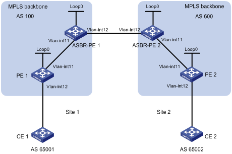
|
设备 |
接口 |
IP地址 |
设备 |
接口 |
IP地址 |
|
PE 1 |
Loop0 |
2.2.2.9/32 |
PE 2 |
Loop0 |
5.5.5.9/32 |
|
|
Vlan-int12 |
30.0.0.1/8 |
|
Vlan-int12 |
20.0.0.1/8 |
|
|
Vlan-int11 |
1.1.1.2/8 |
|
Vlan-int11 |
9.1.1.2/8 |
|
ASBR-PE 1 |
Loop0 |
3.3.3.9/32 |
ASBR-PE 2 |
Loop0 |
4.4.4.9/32 |
|
|
Vlan-int11 |
1.1.1.1/8 |
|
Vlan-int11 |
9.1.1.1/8 |
|
|
Vlan-int12 |
11.0.0.2/8 |
|
Vlan-int12 |
11.0.0.1/8 |
(1) 配置PE 1
# 在PE 1上运行IS-IS。
<PE1> system-view
[PE1] isis 1
[PE1-isis-1] network-entity 10.1111.1111.1111.1111.00
[PE1-isis-1] quit
# 配置LSR ID,使能MPLS和LDP。
[PE1] mpls lsr-id 2.2.2.9
[PE1] mpls
[PE1-mpls] label advertise non-null
[PE1-mpls] quit
[PE1] mpls ldp
[PE1-mpls-ldp] quit
# 配置Vlan-interface11,在接口上运行IS-IS,并使能MPLS和LDP。
[PE1] interface vlan-interface 11
[PE1-Vlan-interface11] ip address 1.1.1.2 255.0.0.0
[PE1-Vlan-interface11] isis enable 1
[PE1-Vlan-interface11] mpls
[PE1-Vlan-interface11] mpls ldp
[PE1-Vlan-interface11] quit
# 创建Loopback0接口,在接口上运行IS-IS。
[PE1] interface loopback 0
[PE1-LoopBack0] ip address 2.2.2.9 32
[PE1-LoopBack0] isis enable 1
[PE1-LoopBack0] quit
# 创建一个VPN实例,名为vpn1,配置RD和VPN Target属性。
[PE1] ip vpn-instance vpn1
[PE1-vpn-instance-vpn1] route-distinguisher 11:11
[PE1-vpn-instance-vpn1] vpn-target 3:3 import-extcommunity
[PE1-vpn-instance-vpn1] vpn-target 3:3 export-extcommunity
[PE1-vpn-instance-vpn1] quit
# 将连接CE 1的接口绑定到创建的VPN实例。
[PE1] interface vlan-interface 12
[PE1-Vlan-interface12] ip binding vpn-instance vpn1
[PE1-Vlan-interface12] ip address 30.0.0.1 8
[PE1-Vlan-interface12] quit
# 在PE 1上运行BGP。
[PE1] bgp 100
# 配置IBGP对等体3.3.3.9为VPNv4对等体。
[PE1-bgp] peer 3.3.3.9 as-number 100
[PE1-bgp] peer 3.3.3.9 connect-interface loopback 0
[PE1-bgp] ipv4-family vpnv4
[PE1-bgp-af-vpnv4] peer 3.3.3.9 enable
[PE1-bgp-af-vpnv4] quit
# 将直连路由引入VPN1的VPN路由表。
[PE1-bgp] ipv4-family vpn-instance vpn1
[PE1-bgp-vpn1] import-route direct
[PE1-bgp-vpn1] quit
[PE1-bgp] quit
(2) 配置ASBR-PE 1
# 在ASBR-PE 1上运行IS-IS。
<ASBR-PE1> system-view
[ASBR-PE1] isis 1
[ASBR-PE1-isis-1] network-entity 10.2222.2222.2222.2222.00
[ASBR-PE1-isis-1] quit
# 配置LSR ID,使能MPLS和LDP。
[ASBR-PE1] mpls lsr-id 3.3.3.9
[ASBR-PE1] mpls
[ASBR-PE1-mpls] label advertise non-null
[ASBR-PE1-mpls] quit
[ASBR-PE1] mpls ldp
[ASBR-PE1-mpls-ldp] quit
# 配置接口Vlan-interface11,在接口上运行IS-IS,并使能MPLS和LDP。
[ASBR-PE1] interface vlan-interface11
[ASBR-PE1-Vlan-interface11] ip address 1.1.1.1 255.0.0.0
[ASBR-PE1-Vlan-interface11] isis enable 1
[ASBR-PE1-Vlan-interface11] mpls
[ASBR-PE1-Vlan-interface11] mpls ldp
[ASBR-PE1-Vlan-interface11] quit
# 配置接口Vlan-interface12,使能MPLS。
[ASBR-PE1] interface vlan-interface 12
[ASBR-PE1-Vlan-interface12] ip address 11.0.0.2 255.0.0.0
[ASBR-PE1-Vlan-interface12] mpls
[ASBR-PE1-Vlan-interface12] quit
# 创建Loopback0接口,并运行IS-IS。
[ASBR-PE1] interface loopback 0
[ASBR-PE1-LoopBack0] ip address 3.3.3.9 32
[ASBR-PE1-LoopBack0] isis enable 1
[ASBR-PE1-LoopBack0] quit
# 在ASBR-PE 1上运行BGP
[ASBR-PE1] bgp 100
[ASBR-PE1-bgp] peer 2.2.2.9 as-number 100
[ASBR-PE1-bgp] peer 2.2.2.9 connect-interface loopback 0
[ASBR-PE1-bgp] peer 11.0.0.1 as-number 600
# 不对接收的VPNv4路由进行Import VPN-target过滤。
[ASBR-PE1-bgp] ipv4-family vpnv4
[ASBR-PE1-bgp-af-vpnv4] undo policy vpn-target
# 将IBGP对等体2.2.2.9和EBGP对等体11.0.0.1都配置为VPNv4对等体。
[ASBR-PE1-bgp-af-vpnv4] peer 11.0.0.1 enable
[ASBR-PE1-bgp-af-vpnv4] peer 2.2.2.9 enable
[ASBR-PE1-bgp-af-vpnv4] quit
(3) 配置ASBR-PE 2
# 在ASBR-PE 2上运行IS-IS。
<ASBR-PE2> system-view
[ASBR-PE2] isis 1
[ASBR-PE2-isis-1] network-entity 10.3333.3333.3333.3333.00
[ASBR-PE2-isis-1] quit
# 配置LSR ID,使能MPLS和LDP。
[ASBR-PE2] mpls lsr-id 4.4.4.9
[ASBR-PE2] mpls
[ASBR-PE2-mpls] label advertise non-null
[ASBR-PE2-mpls] quit
[ASBR-PE2] mpls ldp
[ASBR-PE2-mpls-ldp] quit
# 配置接口Vlan-interface11,在接口上运行IS-IS,并使能MPLS和LDP。
[ASBR-PE2] interface vlan-interface 11
[ASBR-PE2-Vlan-interface11] ip address 9.1.1.1 255.0.0.0
[ASBR-PE2-Vlan-interface11] isis enable 1
[ASBR-PE2-Vlan-interface11] mpls
[ASBR-PE2-Vlan-interface11] mpls ldp
[ASBR-PE2-Vlan-interface11] quit
# 配置接口Vlan-interface12,使能MPLS。
[ASBR-PE2] interface vlan-interface 12
[ASBR-PE2-Vlan-interface12] ip address 11.0.0.1 255.0.0.0
[ASBR-PE2-Vlan-interface12] mpls
[ASBR-PE2-Vlan-interface12] quit
# 创建Loopback0接口,并运行IS-IS。
[ASBR-PE2] interface loopback 0
[ASBR-PE2-LoopBack0] ip address 4.4.4.9 32
[ASBR-PE2-LoopBack0] isis enable 1
[ASBR-PE2-LoopBack0] quit
# 在ASBR-PE 2上运行BGP。
[ASBR-PE2] bgp 600
[ASBR-PE2-bgp] peer 11.0.0.2 as-number 100
[ASBR-PE2-bgp] peer 5.5.5.9 as-number 600
[ASBR-PE2-bgp] peer 5.5.5.9 connect-interface loopback 0
# 不对接收的VPNv4路由进行Import VPN-target过滤。
[ASBR-PE2-bgp] ipv4-family vpnv4
[ASBR-PE2-bgp-af-vpnv4] undo policy vpn-target
# 将IBGP对等体5.5.5.9和EBGP对等体11.0.0.2都配置为VPNv4对等体。
[ASBR-PE2-bgp-af-vpnv4] peer 11.0.0.2 enable
[ASBR-PE2-bgp-af-vpnv4] peer 5.5.5.9 enable
[ASBR-PE2-bgp-af-vpnv4] quit
[ASBR-PE2-bgp] quit
(4) 配置PE 2
# 在PE 2上运行IS-IS。
<PE2> system-view
[PE2] isis 1
[PE2-isis-1] network-entity 10.4444.4444.4444.4444.00
[PE2-isis-1] quit
# 配置LSR ID,使能MPLS和LDP。
[PE2] mpls lsr-id 5.5.5.9
[PE2] mpls
[PE2-mpls] label advertise non-null
[PE2-mpls] quit
[PE2] mpls ldp
[PE2-mpls-ldp] quit
# 配置接口Vlan-interface11,在接口上运行IS-IS,并使能MPLS和LDP。
[PE2] interface vlan-interface 11
[PE2-Vlan-interface11] ip address 9.1.1.2 255.0.0.0
[PE2-Vlan-interface11] isis enable 1
[PE2-Vlan-interface11] mpls
[PE2-Vlan-interface11] mpls ldp
[PE2-Vlan-interface11] quit
# 创建Loopback0接口,在接口上运行IS-IS。
[PE2] interface loopback 0
[PE2-LoopBack0] ip address 5.5.5.9 32
[PE2-LoopBack0] isis enable 1
[PE2-LoopBack0] quit
# 创建一个VPN实例,名为vpn1,配置RD和VPN Target属性。
[PE2] ip vpn-instance vpn1
[PE2-vpn-instance-vpn1] route-distinguisher 12:12
[PE2-vpn-instance-vpn1] vpn-target 3:3 import-extcommunity
[PE2-vpn-instance-vpn1] vpn-target 3:3 export-extcommunity
[PE2-vpn-instance-vpn1] quit
# 将连接CE 2的接口绑定到创建的VPN实例。
[PE2] interface Vlan-interface12
[PE2-Vlan-interface12] ip binding vpn-instance vpn1
[PE2-Vlan-interface12] ip address 20.0.0.1 8
[PE2-Vlan-interface12] quit
# 在PE 2上运行BGP。
[PE2] bgp 600
# 配置IBGP对等体4.4.4.9为VPNv4对等体。
[PE2-bgp] peer 4.4.4.9 as-number 600
[PE2-bgp] peer 4.4.4.9 connect-interface loopback 0
[PE2-bgp] ipv4-family vpnv4
[PE2-bgp-af-vpnv4] peer 4.4.4.9 enable
[PE2-bgp-af-vpnv4] quit
# 将直连路由引入VPN1的VPN路由表。
[PE2-bgp] ipv4-family vpn-instance vpn1
[PE2-bgp-vpn1] import-route direct
[PE2-bgp-vpn1] quit
[PE2-bgp] quit
(5) 配置完成后的检验
# 配置完成后,在PE 2上对PE 1进行Ping操作,可以Ping通:
[PE2] ping –vpn-instance vpn1 30.0.0.1
# 在PE 1上对PE 2进行Ping操作,也可以Ping通:
[PE1] ping –vpn-instance vpn1 20.0.0.1
· Site 1和Site 2属于同一个VPN,Site 1通过AS 100的PE 1接入,Site 2通过AS 600的PE 2接入;
· 同一自治系统内的PE设备之间运行IS-IS作为IGP;
· PE 1与ASBR-PE 1间通过MP-IBGP交换标签IPv4路由;
· PE 2与ASBR-PE 2间通过MP-IBGP交换标签IPv4路由;
· PE 1与PE 2建立MP-EBGP对等体;
· ASBR-PE 1和ASBR-PE 2上分别配置路由策略,对从对方接收的路由压入标签;
· ASBR-PE 1与ASBR-PE 2间通过MP-EBGP交换标签IPv4路由。
图1-24 配置跨域VPN-OptionC方式组网图
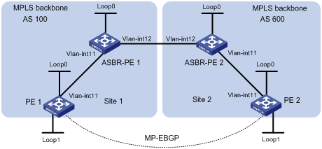
|
设备 |
接口 |
IP地址 |
设备 |
接口 |
IP地址 |
|
PE 1 |
Loop0 |
2.2.2.9/32 |
PE 2 |
Loop0 |
5.5.5.9/32 |
|
|
Loop1 |
30.0.0.1/32 |
|
Loop1 |
20.0.0.1/32 |
|
|
Vlan-int11 |
1.1.1.2/8 |
|
Vlan-int11 |
9.1.1.2/8 |
|
ASBR-PE 1 |
Loop0 |
3.3.3.9/32 |
ASBR-PE 2 |
Loop0 |
4.4.4.9/32 |
|
|
Vlan-int11 |
1.1.1.1/8 |
|
Vlan-int11 |
9.1.1.1/8 |
|
|
Vlan-int12 |
11.0.0.2/8 |
|
Vlan-int12 |
11.0.0.1/8 |
(1) 配置PE 1
# 在PE 1上运行IS-IS。
<PE1> system-view
[PE1] isis 1
[PE1-isis-1] network-entity 10.1111.1111.1111.1111.00
[PE1-isis-1] quit
# 配置LSR ID,使能MPLS和LDP。
[PE1] mpls lsr-id 2.2.2.9
[PE1] mpls
[PE1-mpls] label advertise non-null
[PE1-mpls] quit
[PE1] mpls ldp
[PE1-mpls-ldp] quit
# 配置接口Vlan-interface11,在接口上运行IS-IS,并使能MPLS和LDP。
[PE1] interface vlan-interface 11
[PE1-Vlan-interface11] ip address 1.1.1.2 255.0.0.0
[PE1-Vlan-interface11] isis enable 1
[PE1-Vlan-interface11] mpls
[PE1-Vlan-interface11] mpls ldp
[PE1-Vlan-interface11] quit
# 创建Loopback0接口,在接口上运行IS-IS。
[PE1] interface loopback 0
[PE1-LoopBack0] ip address 2.2.2.9 32
[PE1-LoopBack0] isis enable 1
[PE1-LoopBack0] quit
# 创建VPN实例,名称为vpn1,为其配置RD和VPN Target属性。
[PE1] ip vpn-instance vpn1
[PE1-vpn-instance-vpn1] route-distinguisher 11:11
[PE1-vpn-instance-vpn1] vpn-target 3:3 import-extcommunity
[PE1-vpn-instance-vpn1] vpn-target 3:3 export-extcommunity
[PE1-vpn-instance-vpn1] quit
# 创建Loopback1接口,并将此接口绑定到vpn1。
[PE1] interface loopback 1
[PE1-LoopBack1] ip binding vpn-instance vpn1
[PE1-LoopBack1] ip address 30.0.0.1 32
[PE1-LoopBack1] quit
# 在PE 1上运行BGP。
[PE1] bgp 100
# 配置PE 1向IBGP对等体3.3.3.9发布标签路由及从3.3.3.9接收标签路由的能力。
[PE1-bgp] peer 3.3.3.9 as-number 100
[PE1-bgp] peer 3.3.3.9 connect-interface loopback 0
[PE1-bgp] peer 3.3.3.9 label-route-capability
# 配置PE 1到EBGP对等体5.5.5.9的最大跳数为10。
[PE1-bgp] peer 5.5.5.9 as-number 600
[PE1-bgp] peer 5.5.5.9 connect-interface loopback 0
[PE1-bgp] peer 5.5.5.9 ebgp-max-hop 10
# 配置对等体5.5.5.9作为VPNv4对等体。
[PE1-bgp] ipv4-family vpnv4
[PE1-bgp-af-vpnv4] peer 5.5.5.9 enable
[PE1-bgp-af-vpnv4] quit
# 将直连路由引入vpn1的路由表。
[PE1-bgp] ipv4-family vpn-instance vpn1
[PE1-bgp-vpn1] import-route direct
[PE1-bgp-vpn1] quit
[PE1-bgp] quit
(2) 配置ASBR-PE1
# 在ASBR-PE 1上运行IS-IS。
<ASBR-PE1> system-view
[ASBR-PE1] isis 1
[ASBR-PE1-isis-1] network-entity 10.2222.2222.2222.2222.00
[ASBR-PE1-isis-1] quit
# 配置LSR ID,使能MPLS和LDP。
[ASBR-PE1] mpls lsr-id 3.3.3.9
[ASBR-PE1] mpls
[ASBR-PE1-mpls] label advertise non-null
[ASBR-PE1-mpls] quit
[ASBR-PE1] mpls ldp
[ASBR-PE1-mpls-ldp] quit
# 配置接口Vlan-interface11,在接口上运行IS-IS,并使能MPLS和LDP。
[ASBR-PE1] interface vlan-interface 11
[ASBR-PE1-Vlan-interface11] ip address 1.1.1.1 255.0.0.0
[ASBR-PE1-Vlan-interface11] isis enable 1
[ASBR-PE1-Vlan-interface11] mpls
[ASBR-PE1-Vlan-interface11] mpls ldp
[ASBR-PE1-Vlan-interface11] quit
# 配置接口Vlan-interface12,并在接口上使能MPLS。
[ASBR-PE1] interface vlan-interface 12
[ASBR-PE1-Vlan-interface12] ip address 11.0.0.2 255.0.0.0
[ASBR-PE1-Vlan-interface12] mpls
[ASBR-PE1-Vlan-interface12] quit
# 创建Loopback0接口,在接口上运行IS-IS。
[ASBR-PE1] interface loopback 0
[ASBR-PE1-LoopBack0] ip address 3.3.3.9 32
[ASBR-PE1-LoopBack0] isis enable 1
[ASBR-PE1-LoopBack0] quit
# 创建路由策略。
[ASBR-PE1] route-policy policy1 permit node 1
[ASBR-PE1-route-policy1] apply mpls-label
[ASBR-PE1-route-policy1] quit
[ASBR-PE1] route-policy policy2 permit node 1
[ASBR-PE1-route-policy2] if-match mpls-label
[ASBR-PE1-route-policy2] apply mpls-label
[ASBR-PE1-route-policy2] quit
# 在ASBR-PE 1上运行BGP,引入IS-IS进程1的路由。
[ASBR-PE1] bgp 100
[ASBR-PE1-bgp] import-route isis 1
# 对向IBGP对等体2.2.2.9发布的路由应用已配置的路由策略policy2。
[ASBR-PE1-bgp] peer 2.2.2.9 as-number 100
[ASBR-PE1-bgp] peer 2.2.2.9 route-policy policy2 export
# 向IBGP对等体2.2.2.9发布标签路由及从2.2.2.9接收标签路由的能力。
[ASBR-PE1-bgp] peer 2.2.2.9 connect-interface loopback 0
[ASBR-PE1-bgp] peer 2.2.2.9 label-route-capability
# 对向EBGP对等体11.0.0.1发布的路由应用已配置的路由策略policy1。
[ASBR-PE1-bgp] peer 11.0.0.1 as-number 600
[ASBR-PE1-bgp] peer 11.0.0.1 route-policy policy1 export
# 向EBGP对等体11.0.0.1发布标签路由及从11.0.0.1接收标签路由的能力。
[ASBR-PE1-bgp] peer 11.0.0.1 label-route-capability
[ASBR-PE1-bgp] quit
(3) 配置ASBR-PE 2
# 在ASBR-PE 2上运行IS-IS。
<ASBR-PE2> system-view
[ASBR-PE2] isis 1
[ASBR-PE2-isis-1] network-entity 10.3333.3333.3333.3333.00
[ASBR-PE2-isis-1] quit
# 配置LSR ID,使能MPLS和LDP。
[ASBR-PE2] mpls lsr-id 4.4.4.9
[ASBR-PE2] mpls
[ASBR-PE2-mpls] label advertise non-null
[ASBR-PE2-mpls] quit
[ASBR-PE2] mpls ldp
[ASBR-PE2-mpls-ldp] quit
# 配置接口Vlan-interface11,在接口上运行IS-IS,并在接口上使能MPLS和LDP。
[ASBR-PE2] interface vlan-interface 11
[ASBR-PE2-Vlan-interface11] ip address 9.1.1.1 255.0.0.0
[ASBR-PE2-Vlan-interface11] isis enable 1
[ASBR-PE2-Vlan-interface11] mpls
[ASBR-PE2-Vlan-interface11] mpls ldp
[ASBR-PE2-Vlan-interface11] quit
# 创建Loopback0接口,在接口上运行IS-IS。
[ASBR-PE2] interface loopback 0
[ASBR-PE2-LoopBack0] ip address 4.4.4.9 32
[ASBR-PE2-LoopBack0] isis enable 1
[ASBR-PE2-LoopBack0] quit
# 配置接口Vlan-interface12,在接口上使能MPLS。
[ASBR-PE2] interface vlan-interface 12
[ASBR-PE2-Vlan-interface12] ip address 11.0.0.1 255.0.0.0
[ASBR-PE2-Vlan-interface12] mpls
[ASBR-PE2-Vlan-interface12] quit
# 创建路由策略。
[ASBR-PE2] route-policy policy1 permit node 1
New Sequence of this List
[ASBR-PE2-route-policy1] apply mpls-label
[ASBR-PE2-route-policy1] quit
[ASBR-PE2] route-policy policy2 permit node 1
[ASBR-PE2-route-policy2] if-match mpls-label
[ASBR-PE2-route-policy2] apply mpls-label
[ASBR-PE2-route-policy2] quit
# 在ASBR-PE 2上运行BGP,引入IS-IS进程1的路由。
[ASBR-PE2] bgp 600
[ASBR-PE2-bgp] import-route isis 1
# 向IBGP对等体5.5.5.9发布标签路由及从5.5.5.9接收标签路由的能力。
[ASBR-PE2-bgp] peer 5.5.5.9 as-number 600
[ASBR-PE2-bgp] peer 5.5.5.9 connect-interface loopback 0
[ASBR-PE2-bgp] peer 5.5.5.9 label-route-capability
# 对向IBGP对等体5.5.5.9发布的路由应用已配置的路由策略policy2。
[ASBR-PE2-bgp] peer 5.5.5.9 route-policy policy2 export
# 对向EBGP对等体11.0.0.2发布的路由应用已配置的路由策略policy1。
[ASBR-PE2-bgp] peer 11.0.0.2 as-number 100
[ASBR-PE2-bgp] peer 11.0.0.2 route-policy policy1 export
# 向EBGP对等体11.0.0.2发布标签路由及从11.0.0.2接收标签路由的能力。
[ASBR-PE2-bgp] peer 11.0.0.2 label-route-capability
[ASBR-PE2-bgp] quit
(4) 配置PE 2
# 在PE 2上运行IS-IS。
<PE2> system-view
[PE2] isis 1
[PE2-isis-1] network-entity 10.4444.4444.4444.4444.00
[PE2-isis-1] quit
# 配置LSR ID,使能MPLS和LDP。
[PE2] mpls lsr-id 5.5.5.9
[PE2] mpls
[PE2-mpls] label advertise non-null
[PE2-mpls] quit
[PE2] mpls ldp
[PE2-mpls-ldp] quit
# 配置接口Vlan-interface11,在接口上运行IS-IS,并使能MPLS和LDP。
[PE2] interface vlan-interface 11
[PE2-Vlan-interface11] ip address 9.1.1.2 255.0.0.0
[PE2-Vlan-interface11] isis enable 1
[PE2-Vlan-interface11] mpls
[PE2-Vlan-interface11] mpls ldp
[PE2-Vlan-interface11] quit
# 创建Loopback0接口,在接口上运行IS-IS。
[PE2] interface loopback 0
[PE2-LoopBack0] ip address 5.5.5.9 32
[PE2-LoopBack0] isis enable 1
[PE2-LoopBack0] quit
# 创建VPN实例,名称为vpn1,为其配置RD和VPN Target属性。
[PE2] ip vpn-instance vpn1
[PE2-vpn-instance-vpn1] route-distinguisher 11:11
[PE2-vpn-instance-vpn1] vpn-target 3:3 import-extcommunity
[PE2-vpn-instance-vpn1] vpn-target 3:3 export-extcommunity
[PE2-vpn-instance-vpn1] quit
# 创建Loopback1接口,并将此接口绑定到vpn1。
[PE2] interface loopback 1
[PE2-LoopBack1] ip binding vpn-instance vpn1
[PE2-LoopBack1] ip address 20.0.0.1 32
[PE2-LoopBack1] quit
# 在PE 2上运行BGP。
[PE2] bgp 600
# 配置PE 2向IBGP对等体4.4.4.9发布标签路由及从4.4.4.9接收标签路由的能力。
[PE2-bgp] peer 4.4.4.9 as-number 600
[PE2-bgp] peer 4.4.4.9 connect-interface loopback 0
[PE2-bgp] peer 4.4.4.9 label-route-capability
# 配置PE 2到EBGP对等体2.2.2.9的最大跳数为10。
[PE2-bgp] peer 2.2.2.9 as-number 100
[PE2-bgp] peer 2.2.2.9 connect-interface loopback 0
[PE2-bgp] peer 2.2.2.9 ebgp-max-hop 10
# 配置对等体2.2.2.9作为VPNv4对等体。
[PE2-bgp] ipv4-family vpnv4
[PE2-bgp-af-vpnv4] peer 2.2.2.9 enable
[PE2-bgp-af-vpnv4] quit
# 将直连路由引入vpn1的路由表。
[PE2-bgp] ipv4-family vpn-instance vpn1
[PE2-bgp-vpn1] import-route direct
[PE2-bgp-vpn1] quit
[PE2-bgp] quit
配置完成后,在PE2上对PE1进行Ping操作,可以Ping通:
[PE2] ping –vpn-instance vpn1 30.0.0.1
在PE1上对PE2进行Ping操作,也可以Ping通:
[PE1] ping –vpn-instance vpn1 20.0.0.1
· PE 1和PE 2是一级运营商骨干网的PE设备,为二级运营商提供VPN服务;
· CE 1和CE 2是同一个二级运营商的设备,作为CE接入一级运营商的骨干网;
· PE 3和PE 4是二级运营商的PE设备,为二级运营商的客户提供MPLS L3VPN服务;
· CE 3和CE 4是二级运营商的客户。
配置运营商的运营商关键在于配置两类路由的交换:
· 二级运营商VPN内部路由在一级运营商骨干网上的交换:一级运营商将二级运营商作为自己的CE接入;
· 二级运营商本身客户的VPN路由在二级运营商PE设备间的交换:需要在二级运营商PE设备(PE 3和PE 4)间建立MP-IBGP对等体关系。
图1-25 配置Carriers’ carriers配置组网图
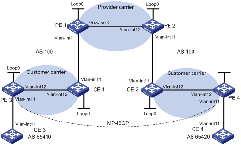
|
设备 |
接口 |
IP地址 |
设备 |
接口 |
IP地址 |
|
CE 3 |
Vlan-int11 |
100.1.1.1/24 |
CE 4 |
Vlan-int11 |
120.1.1.1/24 |
|
PE 3 |
Loop0 |
1.1.1.9/32 |
PE 4 |
Loop0 |
6.6.6.9/32 |
|
|
Vlan-int11 |
100.1.1.2/24 |
|
Vlan-int11 |
120.1.1.2/24 |
|
|
Vlan-int12 |
10.1.1.1/24 |
|
Vlan-int12 |
20.1.1.2/24 |
|
CE 1 |
Loop0 |
2.2.2.9/32 |
CE 2 |
Loop0 |
5.5.5.9/32 |
|
|
Vlan-int12 |
10.1.1.2/24 |
|
Vlan-int11 |
21.1.1.2/24 |
|
|
Vlan-int11 |
11.1.1.1/24 |
|
Vlan-int12 |
20.1.1.1/24 |
|
PE 1 |
Loop0 |
3.3.3.9/32 |
PE 2 |
Loop0 |
4.4.4.9/32 |
|
|
Vlan-int11 |
11.1.1.2/24 |
|
Vlan-int12 |
30.1.1.2/24 |
|
|
Vlan-int12 |
30.1.1.1/24 |
|
Vlan-int11 |
21.1.1.1/24 |
(1) 配置一级运营商骨干网的MPLS L3VPN,使用IS-IS作为骨干网的IGP协议,PE 1和PE 2之间使能LDP,并建立MP-IBGP对等体关系
# 配置PE 1。
<PE1> system-view
[PE1] interface loopback 0
[PE1-LoopBack0] ip address 3.3.3.9 32
[PE1-LoopBack0] quit
[PE1] mpls lsr-id 3.3.3.9
[PE1] mpls
[PE1-mpls] quit
[PE1] mpls ldp
[PE1-mpls-ldp] quit
[PE1] isis 1
[PE1-isis-1] network-entity 10.0000.0000.0000.0004.00
[PE1-isis-1] quit
[PE1] interface loopback 0
[PE1-LoopBack0] isis enable 1
[PE1-LoopBack0] quit
[PE1] interface vlan-interface 12
[PE1-Vlan-interface12] ip address 30.1.1.1 24
[PE1-Vlan-interface12] isis enable 1
[PE1-Vlan-interface12] mpls
[PE1-Vlan-interface12] mpls ldp
[PE1-Vlan-interface12] mpls ldp transport-address interface
[PE1-Vlan-interface12] quit
[PE1] bgp 100
[PE1-bgp] peer 4.4.4.9 as-number 100
[PE1-bgp] peer 4.4.4.9 connect-interface loopback 0
[PE1-bgp] ipv4-family vpnv4
[PE1-bgp-af-vpnv4] peer 4.4.4.9 enable
[PE1-bgp-af-vpnv4] quit
[PE1-bgp] quit
![]()
PE 2的配置与PE 1类似,配置过程省略。
配置完成后,在PE 1或PE 2上执行display mpls ldp session命令可以看到LDP会话建立成功;执行display bgp peer命令可以看到BGP对等体关系已建立,并达到Established状态;执行display isis peer命令可以看到IS-IS邻居关系已建立,状态为up。
以PE1为例:
[PE1] display mpls ldp session
LDP Session(s) in Public Network
Total number of sessions: 1
----------------------------------------------------------------
Peer-ID Status LAM SsnRole FT MD5 KA-Sent/Rcv
----------------------------------------------------------------
4.4.4.9:0 Operational DU Active Off Off 378/378
----------------------------------------------------------------
LAM : Label Advertisement Mode FT : Fault Tolerance
[PE1] display bgp peer
BGP local router ID : 3.3.3.9
Local AS number : 100
Total number of peers : 1 Peers in established state : 1
Peer AS MsgRcvd MsgSent OutQ PrefRcv Up/Down State
4.4.4.9 100 162 145 0 0 02:12:47 Established
[PE1] display isis peer
Peer information for ISIS(1)
----------------------------
System Id Interface Circuit Id State HoldTime Type PRI
0000.0000.0005 Vlan-interface2 001 Up 29s L1L2 --
(2) 配置二级运营商网络:使用IS-IS作为IGP协议,PE 3和CE 1、PE 4和CE 2之间分别使能LDP
# 配置PE 3。
<PE3> system-view
[PE3] interface loopback 0
[PE3-LoopBack0] ip address 1.1.1.9 32
[PE3-LoopBack0] quit
[PE3] mpls lsr-id 1.1.1.9
[PE3] mpls
[PE3-mpls] quit
[PE3] mpls ldp
[PE3-mpls-ldp] quit
[PE3] isis 2
[PE3-isis-2] network-entity 10.0000.0000.0000.0001.00
[PE3-isis-2] quit
[PE3] interface loopback 0
[PE3-LoopBack0] isis enable 2
[PE3-LoopBack0] quit
[PE3] interface vlan-interface 12
[PE3-Vlan-interface12] ip address 10.1.1.1 24
[PE3-Vlan-interface12] isis enable 2
[PE3-Vlan-interface12] mpls
[PE3-Vlan-interface12] mpls ldp
[PE3-Vlan-interface12] mpls ldp transport-address interface
[PE3-Vlan-interface12] quit
# 配置CE 1。
<CE1> system-view
[CE1] interface loopback 0
[CE1-LoopBack0] ip address 2.2.2.9 32
[CE1-LoopBack0] quit
[CE1] mpls lsr-id 2.2.2.9
[CE1] mpls
[CE1-mpls] quit
[CE1] mpls ldp
[CE1-mpls-ldp] quit
[CE1] isis 2
[CE1-isis-2] network-entity 10.0000.0000.0000.0002.00
[CE1-isis-2] quit
[CE1] interface loopback 0
[CE1-LoopBack0] isis enable 2
[CE1-LoopBack0] quit
[CE1] interface vlan-interface 12
[CE1-Vlan-interface12] ip address 10.1.1.2 24
[CE1-Vlan-interface12] isis enable 2
[CE1-Vlan-interface12] mpls
[CE1-Vlan-interface12] mpls ldp
[CE1-Vlan-interface12] mpls ldp transport-address interface
[CE1-Vlan-interface12] quit
配置完成后,PE 3和CE 1之间应能建立LDP和IS-IS邻居关系。
![]()
PE 4和CE 2之间的配置与PE 3和CE 1之间的配置类似,配置过程省略。
(3) 配置二级运营商CE接入到一级运营商的PE,并在PE上配置IS-IS引入BGP路由、BGP引入IS-IS路由
# 配置PE 1。
[PE1] ip vpn-instance vpn1
[PE1-vpn-instance-vpn1] route-distinguisher 200:1
[PE1-vpn-instance-vpn1] vpn-target 1:1
[PE1-vpn-instance-vpn1] quit
[PE1] mpls ldp vpn-instance vpn1
[PE1-mpls-ldp-vpn-instance-vpn1] quit
[PE1] isis 2 vpn-instance vpn1
[PE1-isis-2] network-entity 10.0000.0000.0000.0003.00
[PE1-isis-2] import-route bgp allow-ibgp
[PE1-isis-2] quit
[PE1] interface vlan-interface11
[PE1-Vlan-interface11] ip binding vpn-instance vpn1
[PE1-Vlan-interface11] ip address 11.1.1.2 24
[PE1-Vlan-interface11] isis enable 2
[PE1-Vlan-interface11] mpls
[PE1-Vlan-interface11] mpls ldp
[PE1-Vlan-interface11] mpls ldp transport-address interface
[PE1-Vlan-interface11] quit
[PE1] bgp 100
[PE1-bgp] ipv4-family vpn-instance vpn1
[PE1-bgp-vpn1] import isis 2
[PE1-bgp-vpn1] quit
[PE1-bgp] quit
# 配置CE 1。
[CE1] interface vlan-interface11
[CE1-Vlan-interface11] ip address 11.1.1.1 24
[CE1-Vlan-interface11] isis enable 2
[CE1-Vlan-interface11] mpls
[CE1-Vlan-interface11] mpls ldp
[CE1-Vlan-interface11] mpls ldp transport-address interface
[CE1-Vlan-interface11] quit
配置完成后,PE 1和CE 1之间应能建立LDP和IS-IS邻居关系。
![]()
PE 2和CE 2之间的配置与PE 1和CE 1之间的配置类似,配置过程省略。
(4) 配置二级运营商的客户接入PE
# 配置CE 3。
<CE3> system-view
[CE3] interface vlan-interface11
[CE3-Vlan-interface11] ip address 100.1.1.1 24
[CE3-Vlan-interface11] quit
[CE3] bgp 65410
[CE3-bgp] peer 100.1.1.2 as-number 100
[CE3-bgp] import-route direct
[CE3-bgp] quit
# 配置PE 3。
[PE3] ip vpn-instance vpn1
[PE3-vpn-instance-vpn1] route-distinguisher 100:1
[PE3-vpn-instance-vpn1] vpn-target 1:1
[PE3-vpn-instance-vpn1] quit
[PE3] interface Vlan-interface11
[PE3-Vlan-interface11] ip binding vpn-instance vpn1
[PE3-Vlan-interface11] ip address 100.1.1.2 24
[PE3-Vlan-interface11] quit
[PE3] bgp 100
[PE3-bgp] ipv4-family vpn-instance vpn1
[PE3-bgp-vpn1] peer 100.1.1.1 as-number 65410
[PE3-bgp-vpn1] import-route direct
[PE3-bgp-vpn1] quit
[PE3-bgp] quit
![]()
PE 4和CE 4之间的配置与PE 3和CE 3之间的配置类似,配置过程省略。
(5) 在二级运营商的PE之间建立MP-IBGP对等体关系,交换二级运营商的客户的VPN路由
# 配置PE 3。
[PE3] bgp 100
[PE3-bgp] peer 6.6.6.9 as-number 100
[PE3-bgp] peer 6.6.6.9 connect-interface loopback 0
[PE3-bgp] ipv4-family vpnv4
[PE3-bgp-af-vpnv4] peer 6.6.6.9 enable
[PE3-bgp-af-vpnv4] quit
[PE3-bgp] quit
![]()
PE 4的配置与PE 3类似,配置过程省略。
(6) 配置完成后的检验
所有配置完成后,在PE 1和PE 2上执行display ip routing-table命令,可以看到PE 1和PE 2的公网路由表中只有一级运营商网络的路由。以PE 1为例:
[PE1] display ip routing-table
Routing Tables: Public
Destinations : 7 Routes : 7
Destination/Mask Proto Pre Cost NextHop Interface
3.3.3.9/32 Direct 0 0 127.0.0.1 InLoop0
4.4.4.9/32 ISIS 15 10 30.1.1.2 Vlan12
30.1.1.0/24 Direct 0 0 30.1.1.1 Vlan12
30.1.1.1/32 Direct 0 0 127.0.0.1 InLoop0
30.1.1.2/32 Direct 0 0 30.1.1.2 Vlan12
127.0.0.0/8 Direct 0 0 127.0.0.1 InLoop0
127.0.0.1/32 Direct 0 0 127.0.0.1 InLoop0
在PE 1和PE 2上执行display ip routing-table vpn-instance命令,可以看到VPN路由表中有二级运营商网络的内部路由,但没有二级运营商维护的VPN路由。以PE 1为例:
[PE1] display ip routing-table vpn-instance vpn1
Routing Tables: vpn1
Destinations : 11 Routes : 11
Destination/Mask Proto Pre Cost NextHop Interface
1.1.1.9/32 ISIS 15 20 11.1.1.1 Vlan11
2.2.2.9/32 ISIS 15 10 11.1.1.1 Vlan11
5.5.5.9/32 BGP 255 0 4.4.4.9 NULL0
6.6.6.9/32 BGP 255 0 4.4.4.9 NULL0
10.1.1.0/24 ISIS 15 20 11.1.1.1 Vlan11
11.1.1.0/24 Direct 0 0 11.1.1.1 Vlan11
11.1.1.1/32 Direct 0 0 127.0.0.1 InLoop0
11.1.1.2/32 Direct 0 0 11.1.1.2 Vlan11
20.1.1.0/24 BGP 255 0 4.4.4.9 NULL0
21.1.1.0/24 BGP 255 0 4.4.4.9 NULL0
21.1.1.2/32 BGP 255 0 4.4.4.9 NULL0
在CE 1和CE 2上执行display ip routing-table命令,可以看到公网路由表中有二级运营商网络的内部路由,但没有二级运营商维护的VPN路由。以CE 1为例:
[CE1] display ip routing-table
Routing Tables: Public
Destinations : 16 Routes : 16
Destination/Mask Proto Pre Cost NextHop Interface
1.1.1.9/32 ISIS 15 10 10.1.1.2 Vlan12
2.2.2.9/32 Direct 0 0 127.0.0.1 InLoop0
5.5.5.9/32 ISIS 15 74 11.1.1.2 Vlan11
6.6.6.9/32 ISIS 15 74 11.1.1.2 Vlan11
10.1.1.0/24 Direct 0 0 10.1.1.2 Vlan12
10.1.1.1/32 Direct 0 0 10.1.1.1 Vlan12
10.1.1.2/32 Direct 0 0 127.0.0.1 InLoop0
11.1.1.0/24 Direct 0 0 11.1.1.1 Vlan11
11.1.1.1/32 Direct 0 0 127.0.0.1 InLoop0
11.1.1.2/32 Direct 0 0 11.1.1.2 Vlan11
20.1.1.0/24 ISIS 15 74 11.1.1.2 Vlan11
21.1.1.0/24 ISIS 15 74 11.1.1.2 Vlan11
21.1.1.2/32 ISIS 15 74 11.1.1.2 Vlan11
127.0.0.0/8 Direct 0 0 127.0.0.1 InLoop0
127.0.0.1/32 Direct 0 0 127.0.0.1 InLoop0
在PE 3和PE 4上执行display ip routing-table命令,可以看到公网路由表中有二级运营商网络的内部路由。以PE 3为例:
[PE3] display ip routing-table
Routing Tables: Public
Destinations : 11 Routes : 11
Destination/Mask Proto Pre Cost NextHop Interface
1.1.1.9/32 Direct 0 0 127.0.0.1 InLoop0
2.2.2.9/32 ISIS 15 10 10.1.1.2 Vlan12
5.5.5.9/32 ISIS 15 84 10.1.1.2 Vlan12
6.6.6.9/32 ISIS 15 84 10.1.1.2 Vlan12
10.1.1.0/24 Direct 0 0 10.1.1.1 Vlan12
10.1.1.1/32 Direct 0 0 127.0.0.1 InLoop0
10.1.1.2/32 Direct 0 0 10.1.1.2 Vlan12
11.1.1.0/24 ISIS 15 20 10.1.1.2 Vlan12
20.1.1.0/24 ISIS 15 84 10.1.1.2 Vlan12
21.1.1.0/24 ISIS 15 84 10.1.1.2 Vlan12
21.1.1.2/32 ISIS 15 84 10.1.1.2 Vlan12
127.0.0.0/8 Direct 0 0 127.0.0.1 InLoop0
127.0.0.1/32 Direct 0 0 127.0.0.1 InLoop0
在PE 3和PE 4上执行display ip routing-table vpn-instance命令,可以看到VPN路由表中有远端VPN客户的路由。以PE 3为例:
[PE3] display ip routing-table vpn-instance vpn1
Routing Tables: vpn1
Destinations : 3 Routes : 3
Destination/Mask Proto Pre Cost NextHop Interface
100.1.1.0/24 Direct 0 0 100.1.1.2 Vlan11
100.1.1.2/32 Direct 0 0 127.0.0.1 InLoop0
120.1.1.0/24 BGP 255 0 6.6.6.9 NULL0
PE 3和PE 4可以相互Ping通:
[PE3] ping 20.1.1.2
PING 20.1.1.2: 56 data bytes, press CTRL_C to break
Reply from 20.1.1.2: bytes=56 Sequence=1 ttl=252 time=127 ms
Reply from 20.1.1.2: bytes=56 Sequence=2 ttl=252 time=97 ms
Reply from 20.1.1.2: bytes=56 Sequence=3 ttl=252 time=83 ms
Reply from 20.1.1.2: bytes=56 Sequence=4 ttl=252 time=70 ms
Reply from 20.1.1.2: bytes=56 Sequence=5 ttl=252 time=60 ms
--- 20.1.1.2 ping statistics ---
5 packet(s) transmitted
5 packet(s) received
0.00% packet loss
round-trip min/avg/max = 60/87/127 ms
CE 3和CE 4可以互相Ping通。
[CE3] ping 120.1.1.1
PING 120.1.1.1: 56 data bytes, press CTRL_C to break
Reply from 120.1.1.1: bytes=56 Sequence=1 ttl=252 time=102 ms
Reply from 120.1.1.1: bytes=56 Sequence=2 ttl=252 time=69 ms
Reply from 120.1.1.1: bytes=56 Sequence=3 ttl=252 time=105 ms
Reply from 120.1.1.1: bytes=56 Sequence=4 ttl=252 time=88 ms
Reply from 120.1.1.1: bytes=56 Sequence=5 ttl=252 time=87 ms
--- 120.1.1.1 ping statistics ---
5 packet(s) transmitted
5 packet(s) received
0.00% packet loss
round-trip min/avg/max = 69/90/105 ms
运营商向客户提供嵌套VPN服务。如图1-26所示:
· PE 1和PE 2是运营商骨干网的PE设备,支持嵌套VPN功能;
· CE 1和CE 2是VPN用户的CE设备,接入运营商的骨干网,该CE设备支持发送VPNv4路由;
· PE 3和PE 4是用户网络内部的PE设备,支持MPLS L3VPN;
· CE 3、CE 4、CE 5和CE 6是用户网络内部的子VPN的CE设备;
配置嵌套VPN的关键在于理解子VPN路由在运营商PE设备上的处理过程:
· 运营商PE(PE 1和PE 2)收到用户CE(CE 1和CE 2)发送来的VPNv4路由时,需要将该VPNv4路由的RD更换为用户CE所处VPN的RD,同时将用户CE所处VPN的ERT添加到路由的扩展团体属性列表中,然后再按照一般的VPNv4路由发送出去;
· 为了实现用户网络内部子VPN的路由在用户PE和运营商PE间交换,需要在运营商PE和用户CE间建立MP-EBGP对等体关系。
图1-26 嵌套VPN组网图
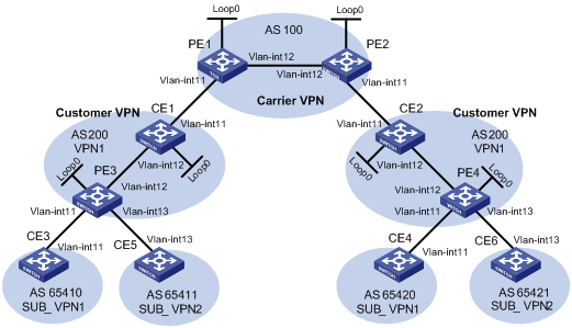
|
设备 |
接口 |
IP地址 |
设备 |
接口 |
IP地址 |
|
CE 1 |
Loop0 |
2.2.2.9/32 |
CE 2 |
Loop0 |
5.5.5.9/32 |
|
|
Vlan-int12 |
10.1.1.2/24 |
|
Vlan-int11 |
21.1.1.2/24 |
|
|
Vlan-int11 |
11.1.1.1/24 |
|
Vlan-int12 |
20.1.1.1/24 |
|
CE 3 |
Vlan-int11 |
100.1.1.1/24 |
CE 4 |
Vlan-int11 |
120.1.1.1/24 |
|
CE 5 |
Vlan-int13 |
110.1.1.1/24 |
CE 6 |
Vlan-int13 |
130.1.1.1/24 |
|
PE 1 |
Loop0 |
3.3.3.9/32 |
PE 2 |
Loop0 |
4.4.4.9/32 |
|
|
Vlan-int11 |
11.1.1.2/24 |
|
Vlan-int11 |
21.1.1.1/24 |
|
|
Vlan-int12 |
30.1.1.1/24 |
|
Vlan-int12 |
30.1.1.2/24 |
|
PE 3 |
Loop0 |
1.1.1.9/32 |
PE 4 |
Loop0 |
6.6.6.9/32 |
|
|
Vlan-int11 |
100.1.1.2/24 |
|
Vlan-int11 |
120.1.1.2/24 |
|
|
Vlan-int12 |
10.1.1.1/24 |
|
Vlan-int12 |
20.1.1.2/24 |
|
|
Vlan-int13 |
110.1.1.2/24 |
|
Vlan-int13 |
130.1.1.2/24 |
(1) 配置运营商骨干网的MPLS L3VPN,使用IS-IS作为骨干网的IGP协议,PE 1和PE 2之间使能LDP,并建立MP-IBGP对等体关系
# 配置PE 1。
<PE1> system-view
[PE1] interface loopback 0
[PE1-LoopBack0] ip address 3.3.3.9 32
[PE1-LoopBack0] quit
[PE1] mpls lsr-id 3.3.3.9
[PE1] mpls
[PE1-mpls] quit
[PE1] mpls ldp
[PE1-mpls-ldp] quit
[PE1] isis 1
[PE1-isis-1] network-entity 10.0000.0000.0000.0004.00
[PE1-isis-1] quit
[PE1] interface loopback 0
[PE1-LoopBack0] isis enable 1
[PE1-LoopBack0] quit
[PE1] interface vlan-interface 12
[PE1-Vlan-interface12] ip address 30.1.1.1 24
[PE1-Vlan-interface12] isis enable 1
[PE1-Vlan-interface12] mpls
[PE1-Vlan-interface12] mpls ldp
[PE1-Vlan-interface12] quit
[PE1] bgp 100
[PE1-bgp] peer 4.4.4.9 as-number 100
[PE1-bgp] peer 4.4.4.9 connect-interface loopback 0
[PE1-bgp] ipv4-family vpnv4
[PE1-bgp-af-vpnv4] peer 4.4.4.9 enable
[PE1-bgp-af-vpnv4] quit
[PE1-bgp] quit
![]()
PE 2的配置与PE 1类似,配置过程省略。
配置完成后,在PE 1或PE 2上执行display mpls ldp session命令可以看到LDP会话建立成功;执行display bgp peer命令可以看到BGP对等体关系已建立,并达到Established状态;执行display isis peer命令可以看到IS-IS邻居关系已建立,状态为up。
以PE 1为例:
[PE1] display mpls ldp session
LDP Session(s) in Public Network
Total number of sessions: 1
----------------------------------------------------------------
Peer-ID Status LAM SsnRole FT MD5 KA-Sent/Rcv
----------------------------------------------------------------
4.4.4.9:0 Operational DU Active Off Off 378/378
----------------------------------------------------------------
LAM : Label Advertisement Mode FT : Fault Tolerance
[PE1] display bgp peer
BGP local router ID : 3.3.3.9
Local AS number : 100
Total number of peers : 1 Peers in established state : 1
Peer AS MsgRcvd MsgSent OutQ PrefRcv Up/Down State
4.4.4.9 100 162 145 0 0 02:12:47 Established
[PE1] display isis peer
Peer information for ISIS(1)
----------------------------
System Id Interface Circuit Id State HoldTime Type PRI
0000.0000.0005 Vlan-interface12 001 Up 29s L1L2 --
(2) 配置用户网络:使用IS-IS作为IGP协议,PE 3和CE 1、PE 4和CE 2之间分别使能LDP
# 配置PE 3。
<PE3> system-view
[PE3] interface loopback 0
[PE3-LoopBack0] ip address 1.1.1.9 32
[PE3-LoopBack0] quit
[PE3] mpls lsr-id 1.1.1.9
[PE3] mpls
[PE3-mpls] quit
[PE3] mpls ldp
[PE3-mpls-ldp] quit
[PE3] isis 2
[PE3-isis-2] network-entity 10.0000.0000.0000.0001.00
[PE3-isis-2] quit
[PE3] interface loopback 0
[PE3-LoopBack0] isis enable 2
[PE3-LoopBack0] quit
[PE3] interface vlan-interface 12
[PE3-Vlan-interface12] ip address 10.1.1.1 24
[PE3-Vlan-interface12] isis enable 2
[PE3-Vlan-interface12] mpls
[PE3-Vlan-interface12] mpls ldp
[PE3-Vlan-interface12] quit
# 配置CE 1。
<CE1> system-view
[CE1] interface loopback 0
[CE1-LoopBack0] ip address 2.2.2.9 32
[CE1-LoopBack0] quit
[CE1] mpls lsr-id 2.2.2.9
[CE1] mpls
[CE1-mpls] quit
[CE1] mpls ldp
[CE1-mpls-ldp] quit
[CE1] isis 2
[CE1-isis-2] network-entity 10.0000.0000.0000.0002.00
[CE1-isis-2] quit
[CE1] interface loopback 0
[CE1-LoopBack0] isis enable 2
[CE1-LoopBack0] quit
[CE1] interface vlan-interface 12
[CE1-Vlan-interface12] ip address 10.1.1.2 24
[CE1-Vlan-interface12] isis enable 2
[CE1-Vlan-interface12] mpls
[CE1-Vlan-interface12] mpls ldp
[CE1-Vlan-interface12] quit
配置完成后,PE 3和CE 1之间可以建立LDP和IS-IS邻居关系。
![]()
PE 4和CE 2之间的配置与PE 3和CE 1之间的配置类似,配置过程省略。
(3) 配置用户CE接入到运营商的PE
# 配置PE 1
[PE1] ip vpn-instance vpn1
[PE1-vpn-instance-vpn1] route-distinguisher 200:1
[PE1-vpn-instance-vpn1] vpn-target 1:1
[PE1-vpn-instance-vpn1] quit
[PE1] interface vlan-interface 11
[PE1-Vlan-interface11] ip binding vpn-instance vpn1
[PE1-Vlan-interface11] ip address 11.1.1.2 24
[PE1-Vlan-interface11] mpls
[PE1-Vlan-interface11] quit
[PE1] bgp 100
[PE1-bgp] ipv4-family vpn-instance vpn1
[PE1-bgp-vpn1] peer 11.1.1.1 as-number 200
[PE1-bgp-vpn1] quit
[PE1-bgp] quit
# 配置CE 1。
[CE1] interface vlan-interface 11
[CE1-Vlan-interface11] ip address 11.1.1.1 24
[CE1-Vlan-interface11] mpls
[CE1-Vlan-interface11] quit
[CE1] bgp 200
[CE1-bgp] peer 11.1.1.2 as-number 100
[CE1-bgp] import isis 2
[CE1-bgp] quit
![]()
PE 2和CE 2之间的配置与PE 1和CE 1之间的配置类似,配置过程省略。
(4) 配置子VPN的CE接入用户网络的PE
# 配置CE 3。
<CE3> system-view
[CE3] interface vlan-interface 11
[CE3-Vlan-interface11] ip address 100.1.1.1 24
[CE3-Vlan-interface11] quit
[CE3] bgp 65410
[CE3-bgp] peer 100.1.1.2 as-number 200
[CE3-bgp] import-route direct
[CE3-bgp] quit
# 配置CE 5。
<CE5> system-view
[CE5] interface vlan-interface 13
[CE5-Vlan-interface13] ip address 110.1.1.1 24
[CE5-Vlan-interface13] quit
[CE5] bgp 65411
[CE5-bgp] peer 110.1.1.2 as-number 200
[CE5-bgp] import-route direct
[CE5-bgp] quit
# 配置PE 3。
[PE3] ip vpn-instance SUB_VPN1
[PE3-vpn-instance-SUB_VPN1] route-distinguisher 100:1
[PE3-vpn-instance-SUB_VPN1] vpn-target 2:1
[PE3-vpn-instance-SUB_VPN1] quit
[PE3] interface vlan-interface 11
[PE3-Vlan-interface11] ip binding vpn-instance SUB_VPN1
[PE3-Vlan-interface11] ip address 100.1.1.2 24
[PE3-Vlan-interface11] quit
[PE3] ip vpn-instance SUB_VPN2
[PE3-vpn-instance-SUB_VPN2] route-distinguisher 101:1
[PE3-vpn-instance-SUB_VPN2] vpn-target 2:2
[PE3-vpn-instance-SUB_VPN2] quit
[PE3] interface vlan-interface 13
[PE3-Vlan-interface13] ip binding vpn-instance SUB_VPN2
[PE3-Vlan-interface13] ip address 110.1.1.2 24
[PE3-Vlan-interface13] quit
[PE3] bgp 200
[PE3-bgp] ipv4-family vpn-instance SUB_VPN1
[PE3-bgp-SUB_VPN1] peer 100.1.1.1 as-number 65410
[PE3-bgp-SUB_VPN1] import-route direct
[PE3-bgp-SUB_VPN1] quit
[PE3-bgp] ipv4-family vpn-instance SUB_VPN2
[PE3-bgp-SUB_VPN2] peer 100.1.1.1 as-number 65411
[PE3-bgp-SUB_VPN2] import-route direct
[PE3-bgp-SUB_VPN2] quit
[PE3-bgp] quit
![]()
PE 4和CE 4,CE 6之间的配置与PE 3和CE 3,CE 5之间的配置类似,配置过程省略。
(5) 在运营商的PE和用户的CE之间建立MP-EBGP对等体关系,交换用户的VPNv4路由
# 配置PE 1,使能嵌套VPN特性。
[PE1] bgp 100
[PE1-bgp] ipv4-family vpnv4
[PE1-bgp-af-vpnv4] nesting-vpn
[PE1-bgp-af-vpnv4] peer 11.1.1.1 vpn-instance vpn1 enable
[PE1-bgp-af-vpnv4] quit
[PE1-bgp] quit
# 配置CE 1,使能VPNv4能力,使之与PE 1建立VPNv4邻居关系。
[CE1] bgp 200
[CE1-bgp] ipv4-family vpnv4
[CE1-bgp-af-vpnv4] peer 11.1.1.2 enable
# 配置允许本地AS号在所接收的路由的AS_PATH属性中出现。
[CE1-bgp-af-vpnv4] peer 11.1.1.2 allow-as-loop 2
# 配置接收所有VPNv4路由。
[CE1-bgp-af-vpnv4] undo policy vpn-target
[CE1-bgp-af-vpnv4] quit
[CE1-bgp] quit
![]()
PE 2和CE 2之间的配置与PE 1和CE 1之间的配置类似,配置过程省略。
(6) 在用户网络内部的PE和CE之间建立MP-IBGP对等体关系,交换用户内部子VPN的VPNv4路由
# 配置PE 3。
[PE3] bgp 200
[PE3-bgp] peer 2.2.2.9 as-number 200
[PE3-bgp] peer 2.2.2.9 connect-interface loopback 0
[PE3-bgp] ipv4-family vpnv4
[PE3-bgp-af-vpnv4] peer 2.2.2.9 enable
# 配置允许本地AS号在所接收的路由的AS_PATH属性中出现。
[PE3-bgp-af-vpnv4] peer 2.2.2.9 allow-as-loop 2
[PE3-bgp-af-vpnv4] quit
[PE3-bgp] quit
# 配置CE 1。
[CE1] bgp 200
[CE1-bgp] peer 1.1.1.9 as-number 200
[CE1-bgp] peer 1.1.1.9 connect-interface loopback 0
[CE1-bgp] ipv4-family vpnv4
[CE1-bgp-af-vpnv4] peer 1.1.1.9 enable
[CE1-bgp-af-vpnv4]undo policy vpn-target
[CE1-bgp-af-vpnv4] quit
[CE1-bgp] quit
![]()
PE 4和CE 2之间的配置与PE 3和CE 1之间的配置类似,配置过程省略。
(7) 配置完成后的检验
所有配置完成后,在PE 1和PE 2上执行display ip routing-table命令,可以看到PE 1和PE 2的公网路由表中只有运营商网络的路由。以PE 1为例:
[PE1] display ip routing-table
Routing Tables: Public
Destinations : 7 Routes : 7
Destination/Mask Proto Pre Cost NextHop Interface
3.3.3.9/32 Direct 0 0 127.0.0.1 InLoop0
4.4.4.9/32 ISIS 15 10 30.1.1.2 Vlan12
30.1.1.0/24 Direct 0 0 30.1.1.1 Vlan12
30.1.1.1/32 Direct 0 0 127.0.0.1 InLoop0
30.1.1.2/32 Direct 0 0 30.1.1.2 Vlan12
127.0.0.0/8 Direct 0 0 127.0.0.1 InLoop0
127.0.0.1/32 Direct 0 0 127.0.0.1 InLoop0
在PE 1和PE 2上执行display ip routing-table vpn-instance命令,可以看到VPN路由表中有用户子VPN网络的路由。以PE 1为例:
[PE1] display ip routing-table vpn-instance vpn1
Routing Tables: vpn1
Destinations : 9 Routes : 9
Destination/Mask Proto Pre Cost NextHop Interface
11.1.1.0/24 Direct 0 0 11.1.1.1 Vlan11
11.1.1.1/32 Direct 0 0 127.0.0.1 InLoop0
11.1.1.2/32 Direct 0 0 11.1.1.2 Vlan11
100.1.1.0/24 BGP 255 0 11.1.1.1 NULL0
110.1.1.0/24 BGP 255 0 11.1.1.1 NULL0
120.1.1.0/24 BGP 255 0 4.4.4.9 NULL0
127.0.0.0/8 Direct 0 0 127.0.0.1 InLoop0
127.0.0.1/32 Direct 0 0 127.0.0.1 InLoop0
130.1.1.0/24 BGP 255 0 4.4.4.9 NULL0
在CE 1和CE 2上执行display bgp vpnv4 all routing-table命令,可以看到用户网络中VPNv4路由表中有子VPN网络的内部路由。以CE 1为例:
[CE1] display bgp vpnv4 all routing-table
BGP Local router ID is 11.11.11.11
Status codes: * - valid, ^ - VPN best, > - best, d - damped,
h - history, i - internal, s - suppressed, S - Stale
Origin : i - IGP, e - EGP, ? - incomplete
Total number of routes from all PE: 4
Route Distinguisher: 100:1
Network NextHop In/Out Label MED LocPrf
*> 100.1.1.0/24 1.1.1.9 1024/1024
Route Distinguisher: 101:1
Network NextHop In/Out Label MED LocPrf
*^ 100.1.1.0/24 1.1.1.9 1024/1024
Route Distinguisher: 101:1
Network NextHop In/Out Label MED LocPrf
* > 110.1.1.0/24 1.1.1.9 1025/1025
Route Distinguisher: 200:1
Network NextHop In/Out Label MED LocPrf
* > 120.1.1.0/24 11.1.1.2 1026/1027
Route Distinguisher: 201:1
Network NextHop In/Out Label MED LocPrf
* > 130.1.1.0/24 11.1.1.2 1027/1028
在PE 3和PE 4上执行display ip routing-table vpn-instance SUB_VPN1命令,可以看到私网路由表中有从运营商PE发布到用户网络子VPN内部的路由。以PE 3为例:
[PE3] display ip routing-table vpn-instance SUB_VPN1
Routing Tables: SUB_VPN1
Destinations : 5 Routes : 5
Destination/Mask Proto Pre Cost NextHop Interface
100.1.1.0/24 Direct 0 0 100.1.1.2 Vlan11
100.1.1.2/32 Direct 0 0 127.0.0.1 InLoop0
120.1.1.0/24 BGP 255 0 2.2.2.9 NULL0
127.0.0.0/8 Direct 0 0 127.0.0.1 InLoop0
127.0.0.1/32 Direct 0 0 127.0.0.1 InLoop0
在CE 3和CE 4上执行display ip routing-table命令,可以看到路由表中有远端子VPN的路由。以CE 3为例:
[CE3] display ip routing-table
Routing Tables: Public
Destinations : 5 Routes : 5
Destination/Mask Proto Pre Cost NextHop Interface
100.1.1.0/24 Direct 0 0 100.1.1.1 Vlan11
100.1.1.1/32 Direct 0 0 127.0.0.1 InLoop0
120.1.1.0/24 BGP 255 0 100.1.1.2 Vlan11
127.0.0.0/8 Direct 0 0 127.0.0.1 InLoop0
127.0.0.1/32 Direct 0 0 127.0.0.1 InLoop0
在CE 5和CE 6上执行display ip routing-table命令,可以看到路由表中有远端子VPN的路由。以CE 5为例:
[CE5] display ip routing-table
Routing Tables: Public
Destinations : 5 Routes : 5
Destination/Mask Proto Pre Cost NextHop Interface
110.1.1.0/24 Direct 0 0 110.1.1.1 Vlan11
110.1.1.1/32 Direct 0 0 127.0.0.1 InLoop0
127.0.0.0/8 Direct 0 0 127.0.0.1 InLoop0
127.0.0.1/32 Direct 0 0 127.0.0.1 InLoop0
130.1.1.0/24 BGP 255 0 110.1.1.2 Vlan11
CE 3和CE 4可以互相Ping通。
[CE3] ping 120.1.1.1
PING 120.1.1.1: 56 data bytes, press CTRL_C to break
Reply from 120.1.1.1: bytes=56 Sequence=1 ttl=252 time=102 ms
Reply from 120.1.1.1: bytes=56 Sequence=2 ttl=252 time=69 ms
Reply from 120.1.1.1: bytes=56 Sequence=3 ttl=252 time=105 ms
Reply from 120.1.1.1: bytes=56 Sequence=4 ttl=252 time=88 ms
Reply from 120.1.1.1: bytes=56 Sequence=5 ttl=252 time=87 ms
--- 120.1.1.1 ping statistics ---
5 packet(s) transmitted
5 packet(s) received
0.00% packet loss
round-trip min/avg/max = 69/90/105 ms
CE 5和CE 6可以互相Ping通。
[CE5] ping 130.1.1.1
PING 130.1.1.1: 56 data bytes, press CTRL_C to break
Reply from 130.1.1.1: bytes=56 Sequence=1 ttl=252 time=102 ms
Reply from 130.1.1.1: bytes=56 Sequence=2 ttl=252 time=69 ms
Reply from 130.1.1.1: bytes=56 Sequence=3 ttl=252 time=105 ms
Reply from 130.1.1.1: bytes=56 Sequence=4 ttl=252 time=88 ms
Reply from 130.1.1.1: bytes=56 Sequence=5 ttl=252 time=87 ms
--- 130.1.1.1 ping statistics ---
5 packet(s) transmitted
5 packet(s) received
0.00% packet loss
round-trip min/avg/max = 69/90/105 ms
CE 3和CE 6不能互相Ping通。
[CE3] ping 130.1.1.1
PING 130.1.1.1: 56 data bytes, press CTRL_C to break
Request time out
Request time out
Request time out
Request time out
Request time out
--- 130.1.1.1 ping statistics ---
5 packet(s) transmitted
0 packet(s) received
100.00% packet loss
以一个包括省骨干和地市的MPLS VPN网络为例:
· SPE作为省网的PE设备,接入地市的MPLS VPN网络;
· UPE作为下层地市网络的PE设备,最终接入VPN客户。对UPE的性能要求低于对SPE的性能要求。
· SPE将通过路由策略的路由发送给UPE,限制不同Site之间的互相访问权限,使得VPN 1内的CE 1和CE 3可以互相访问,VPN 2内的CE 2和CE 4不能互相访问。
图1-27 配置HoVPN组网图
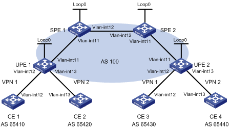
|
设备 |
接口 |
IP地址 |
设备 |
接口 |
IP地址 |
|
CE 1 |
Vlan-int12 |
10.2.1.1/24 |
CE 3 |
Vlan-int12 |
10.1.1.1/24 |
|
CE 2 |
Vlan-int13 |
10.4.1.1/24 |
CE 4 |
Vlan-int13 |
10.3.1.1/24 |
|
UPE 1 |
Loop0 |
1.1.1.9/32 |
UPE 2 |
Loop0 |
4.4.4.9/32 |
|
|
Vlan-int11 |
172.1.1.1/24 |
|
Vlan-int11 |
172.2.1.1/24 |
|
|
Vlan-int12 |
10.2.1.2/24 |
|
Vlan-int12 |
10.1.1.2/24 |
|
|
Vlan-int13 |
10.4.1.2/24 |
|
Vlan-int13 |
10.3.1.2/24 |
|
SPE 1 |
Loop0 |
2.2.2.9/32 |
SPE 2 |
Loop0 |
3.3.3.9/32 |
|
|
Vlan-int11 |
172.1.1.2/24 |
|
Vlan-int11 |
172.2.1.2/24 |
|
|
Vlan-int12 |
180.1.1.1/24 |
|
Vlan-int12 |
180.1.1.2/24 |
(1) 配置UPE 1
# 配置MPLS基本能力和MPLS LDP能力,建立LDP LSP。
<UPE1> system-view
[UPE1] interface loopback 0
[UPE1-LoopBack0] ip address 1.1.1.9 32
[UPE1-LoopBack0] quit
[UPE1] mpls lsr-id 1.1.1.9
[UPE1] mpls
[UPE1-mpls] quit
[UPE1] mpls ldp
[UPE1-mpls-ldp] quit
[UPE1] interface vlan-interface 11
[UPE1-Vlan-interface11] ip address 172.1.1.1 24
[UPE1-Vlan-interface11] mpls
[UPE1-Vlan-interface11] mpls ldp
[UPE1-Vlan-interface11] quit
# 配置IGP协议,以OSPF为例。
[UPE1] ospf
[UPE1-ospf-1] area 0
[UPE1-ospf-1-area-0.0.0.0] network 172.1.1.0 0.0.0.255
[UPE1-ospf-1-area-0.0.0.0] network 1.1.1.9 0.0.0.0
[UPE1-ospf-1-area-0.0.0.0] quit
[UPE1-ospf-1] quit
# 配置VPN实例vpn1和vpn2,将CE 1和CE 2接入UPE 1。
[UPE1] ip vpn-instance vpn1
[UPE1-vpn-instance-vpn1] route-distinguisher 100:1
[UPE1-vpn-instance-vpn1] vpn-target 100:1 both
[UPE1-vpn-instance-vpn1] quit
[UPE1] ip vpn-instance vpn2
[UPE1-vpn-instance-vpn2] route-distinguisher 100:2
[UPE1-vpn-instance-vpn2] vpn-target 100:2 both
[UPE1-vpn-instance-vpn2] quit
[UPE1] interface vlan-interface 12
[UPE1-Vlan-interface12] ip binding vpn-instance vpn1
[UPE1-Vlan-interface12] ip address 10.2.1.2 24
[UPE1-Vlan-interface12] quit
[UPE1] interface vlan-interface 13
[UPE1-Vlan-interface13] ip binding vpn-instance vpn2
[UPE1-Vlan-interface13] ip address 10.4.1.2 24
[UPE1-Vlan-interface13] quit
# 配置UPE 1与SPE 1建立MP-IBGP对等体,并引入VPN路由。
[UPE1] bgp 100
[UPE1-bgp] peer 2.2.2.9 as-number 100
[UPE1-bgp] peer 2.2.2.9 connect-interface loopback 0
[UPE1-bgp] ipv4-family vpnv4
[UPE1-bgp-af-vpnv4] peer 2.2.2.9 enable
[UPE1-bgp-af-vpnv4] quit
[UPE1-bgp] ipv4-family vpn-instance vpn1
[UPE1-bgp-vpn1] peer 10.2.1.1 as-number 65410
[UPE1-bgp-vpn1] import-route direct
[UPE1-bgp-vpn1] quit
[UPE1-bgp] ipv4-family vpn-instance vpn2
[UPE1-bgp-vpn1] peer 10.4.1.1 as-number 65420
[UPE1-bgp-vpn1] import-route direct
[UPE1-bgp-vpn1] quit
[UPE1-bgp] quit
(2) 配置CE 1
<CE1> system-view
[CE1] interface vlan-interface 12
[CE1-Vlan-interface12] ip address 10.2.1.1 255.255.255.0
[CE1-Vlan-interface12] quit
[CE1] bgp 65410
[CE1-bgp] peer 10.2.1.2 as-number 100
[CE1-bgp] import-route direct
[CE1] quit
(3) 配置CE 2
<CE2> system-view
[CE2] interface vlan-interface 13
[CE2-Vlan-interface13] ip address 10.4.1.1 255.255.255.0
[CE2-Vlan-interface13] quit
[CE2] bgp 65420
[CE2-bgp] peer 10.4.1.2 as-number 100
[CE2-bgp] import-route direct
[CE2] quit
(4) 配置UPE 2
# 配置MPLS基本能力和MPLS LDP能力,建立LDP LSP。
<UPE2> system-view
[UPE2] interface loopback 0
[UPE2-Loopback0] ip address 4.4.4.9 32
[UPE2-Loopback0] quit
[UPE2] mpls lsr-id 4.4.4.9
[UPE2] mpls
[UPE2-mpls] quit
[UPE2] mpls ldp
[UPE2-mpls-ldp] quit
[UPE2] interface vlan-interface 11
[UPE2-Vlan-interface11] ip address 172.2.1.1 24
[UPE2-Vlan-interface11] mpls
[UPE2-Vlan-interface11] mpls ldp
[UPE2-Vlan-interface11] quit
# 配置IGP协议,以OSPF为例。
[UPE2] ospf
[UPE2-ospf-1] area 0
[UPE2-ospf-1-area-0.0.0.0] network 172.2.1.0 0.0.0.255
[UPE2-ospf-1-area-0.0.0.0] network 4.4.4.9 0.0.0.0
[UPE2-ospf-1-area-0.0.0.0] quit
[UPE2-ospf-1] quit
# 配置VPN实例vpn1和vpn2,将CE 3和CE 4接入UPE 2。
[UPE2] ip vpn-instance vpn1
[UPE2-vpn-instance-vpn1] route-distinguisher 300:1
[UPE2-vpn-instance-vpn1] vpn-target 100:1 both
[UPE2-vpn-instance-vpn1] quit
[UPE2] ip vpn-instance vpn2
[UPE2-vpn-instance-vpn2] route-distinguisher 400:2
[UPE2-vpn-instance-vpn2] vpn-target 100:2 both
[UPE2-vpn-instance-vpn2] quit
[UPE2] interface vlan-interface 12
[UPE2-Vlan-interface12] ip binding vpn-instance vpn1
[UPE2-Vlan-interface12] ip address 10.1.1.2 24
[UPE2-Vlan-interface12] quit
[UPE2] interface vlan-interface 13
[UPE2-Vlan-interface13] ip binding vpn-instance vpn2
[UPE2-Vlan-interface13] ip address 10.3.1.2 24
[UPE2-Vlan-interface13] quit
# 配置UPE 2与SPE 2建立MP-IBGP对等体,并引入VPN路由。
[UPE2] bgp 100
[UPE2-bgp] peer 3.3.3.9 as-number 100
[UPE2-bgp] peer 3.3.3.9 connect-interface loopback 0
[UPE2-bgp] ipv4-family vpnv4
[UPE2-bgp-af-vpnv4] peer 3.3.3.9 enable
[UPE2-bgp-af-vpnv4] quit
[UPE2-bgp] ipv4-family vpn-instance vpn1
[UPE2-bgp-vpn1] peer 10.1.1.1 as-number 65430
[UPE2-bgp-vpn1] import-route direct
[UPE2-bgp-vpn1] quit
[UPE2-bgp] ipv4-family vpn-instance vpn2
[UPE2-bgp-vpn1] peer 10.3.1.1 as-number 65440
[UPE2-bgp-vpn1] import-route direct
[UPE2-bgp-vpn1] quit
[UPE2-bgp] quit
(5) 配置CE 3
<CE3> system-view
[CE3] interface vlan-interface 12
[CE3-Vlan-interface12] ip address 10.1.1.1 255.255.255.0
[CE3-Vlan-interface12] quit
[CE3] bgp 65430
[CE3-bgp] peer 10.1.1.2 as-number 100
[CE3-bgp] import-route direct
[CE3] quit
(6) 配置CE 4
<CE4> system-view
[CE4] interface vlan-interface 13
[CE4-Vlan-interface13] ip address 10.3.1.1 255.255.255.0
[CE4-Vlan-interface13] quit
[CE4] bgp 65440
[CE4-bgp] peer 10.3.1.2 as-number 100
[CE4-bgp] import-route direct
[CE4] quit
(7) 配置SPE 1
# 配置MPLS基本能力和MPLS LDP能力,建立LDP LSP。
<SPE1> system-view
[SPE1] interface loopback 0
[SPE1-LoopBack0] ip address 2.2.2.9 32
[SPE1-LoopBack0] quit
[SPE1] mpls lsr-id 2.2.2.9
[SPE1] mpls
[SPE1-mpls] quit
[SPE1] mpls ldp
[SPE1-mpls-ldp] quit
[SPE1] interface vlan-interface 11
[SPE1-Vlan-interface11] ip address 172.1.1.2 24
[SPE1-Vlan-interface11] mpls
[SPE1-Vlan-interface11] mpls ldp
[SPE1-Vlan-interface11] quit
[SPE1] interface vlan-interface 12
[SPE1-Vlan-interface12] ip address 180.1.1.1 24
[SPE1-Vlan-interface12] mpls
[SPE1-Vlan-interface12] mpls ldp
[SPE1-Vlan-interface12] quit
# 配置IGP协议,以OSPF为例。
[SPE1] ospf
[SPE1-ospf-1] area 0
[SPE1-ospf-1-area-0.0.0.0] network 2.2.2.9 0.0.0.0
[SPE1-ospf-1-area-0.0.0.0] network 172.1.1.0 0.0.0.255
[SPE1-ospf-1-area-0.0.0.0] network 180.1.1.0 0.0.0.255
[SPE1-ospf-1-area-0.0.0.0] quit
[SPE1-ospf-1] quit
# 配置VPN实例vpn1和vpn2。
[SPE1] ip vpn-instance vpn1
[SPE1-vpn-instance-vpn1] route-distinguisher 500:1
[SPE1-vpn-instance-vpn1 ] vpn-target 100:1 both
[SPE1-vpn-instance-vpn1] quit
[SPE1] ip vpn-instance vpn2
[SPE1-vpn-instance-vpn2] route-distinguisher 700:1
[SPE1-vpn-instance-vpn2] vpn-target 100:2 both
[SPE1-vpn-instance-vpn2] quit
# 配置SPE 1与UPE 1建立MP-IBGP对等体,指定UPE 1,并引入VPN路由。
[SPE1] bgp 100
[SPE1-bgp] peer 1.1.1.9 as-number 100
[SPE1-bgp] peer 1.1.1.9 connect-interface loopback 0
[SPE1-bgp] peer 1.1.1.9 next-hop-local
[SPE1-bgp] peer 3.3.3.9 as-number 100
[SPE1-bgp] peer 3.3.3.9 connect-interface loopback 0
[SPE1-bgp] ipv4-family vpnv4
[SPE1-bgp-af-vpnv4] peer 3.3.3.9 enable
[SPE1-bgp-af-vpnv4] peer 1.1.1.9 enable
[SPE1-bgp-af-vpnv4] peer 1.1.1.9 upe
[SPE1-bgp-af-vpnv4] quit
[SPE1-bgp]ipv4-family vpn-instance vpn1
[SPE1-bgp-vpn1] quit
[SPE1-bgp]ipv4-family vpn-instance vpn2
[SPE1-bgp-vpn2] quit
[SPE1-bgp] quit
# 配置SPE 1向UPE 1发送通过策略的路由信息,允许CE 3的路由发送给UPE 1。
[SPE1] ip ip-prefix hope index 10 permit 10.1.1.1 24
[SPE1] route-policy hope permit node 0
[SPE1-route-policy] if-match ip-prefix hope
[SPE1-route-policy] quit
[SPE1] bgp 100
[SPE1-bgp] ipv4-family vpnv4
[SPE1-bgp-af-vpnv4] peer 1.1.1.9 upe route-policy hope export
(8) 配置SPE 2
# 配置MPLS基本能力和MPLS LDP能力,建立LDP LSP。
<SPE2> system-view
[SPE2] interface loopback 0
[SPE2-LoopBack0] ip address 3.3.3.9 32
[SPE2-LoopBack0] quit
[SPE2] mpls lsr-id 3.3.3.9
[SPE2] mpls
[SPE2-mpls] quit
[SPE2] mpls ldp
[SPE2-mpls-ldp] quit
[SPE2] interface vlan-interface 12
[SPE2-Vlan-interface12] ip address 180.1.1.2 24
[SPE2-Vlan-interface12] mpls
[SPE2-Vlan-interface12] mpls ldp
[SPE2-Vlan-interface12] quit
[SPE2] interface vlan-interface 11
[SPE2-Vlan-interface11] ip address 172.2.1.2 24
[SPE2-Vlan-interface11] mpls
[SPE2-Vlan-interface11] mpls ldp
[SPE2-Vlan-interface11] quit
# 配置IGP协议,以OSPF为例。
[SPE2] ospf
[SPE2-ospf-1] area 0
[SPE2-ospf-1-area-0.0.0.0] network 3.3.3.9 0.0.0.0
[SPE2-ospf-1-area-0.0.0.0] network 172.2.1.0 0.0.0.255
[SPE2-ospf-1-area-0.0.0.0] network 180.1.1.0 0.0.0.255
[SPE2-ospf-1-area-0.0.0.0] quit
[SPE2-ospf-1] quit
# 配置VPN实例vpn1和vpn2。
[SPE2] ip vpn-instance vpn1
[SPE2-vpn-instance-vpn1] route-distinguisher 600:1
[SPE2-vpn-instance-vpn1 ] vpn-target 100:1 both
[SPE2-vpn-instance-vpn1] quit
[SPE2] ip vpn-instance vpn2
[SPE2-vpn-instance-vpn2] route-distinguisher 800:1
[SPE2-vpn-instance-vpn2] vpn-target 100:2 both
[SPE2-vpn-instance-vpn2] quit
# 配置SPE 2与UPE 2建立MP-IBGP对等体,指定UPE 2,并引入VPN路由。
[SPE2] bgp 100
[SPE2-bgp] peer 4.4.4.9 as-number 100
[SPE2-bgp] peer 4.4.4.9 connect-interface loopback 0
[SPE2-bgp] peer 4.4.4.9 next-hop-local
[SPE2-bgp] peer 2.2.2.9 as-number 100
[SPE2-bgp] peer 2.2.2.9 connect-interface loopback 0
[SPE2-bgp] ipv4-family vpnv4
[SPE2-bgp-af-vpnv4] peer 2.2.2.9 enable
[SPE2-bgp-af-vpnv4] peer 4.4.4.9 enable
[SPE2-bgp-af-vpnv4] peer 4.4.4.9 upe
[SPE2-bgp-af-vpnv4] quit
[SPE2-bgp]ipv4-family vpn-instance vpn1
[SPE2-bgp-vpn1] quit
[SPE2-bgp]ipv4-family vpn-instance vpn2
[SPE2-bgp-vpn2] quit
[SPE2-bgp] quit
# 配置SPE 2向UPE 2发送通过策略的路由信息,允许CE 1的路由发送给UPE 2。
[SPE2] ip ip-prefix hope index 10 permit 10.2.1.1 24
[SPE2] route-policy hope permit node 0
[SPE2-route-policy] if-match ip-prefix hope
[SPE2-route-policy] quit
[SPE2] bgp 100
[SPE2-bgp] ipv4-family vpnv4
[SPE2-bgp-af-vpnv4] peer 4.4.4.9 upe route-policy hope export
· CE 1和CE 2都属于VPN 1,它们分别接入PE 1和PE 2;
· CE 1和CE 2在同一个OSPF区域中;
· CE 1与CE 2之间的VPN流量通过MPLS骨干网转发,不使用OSPF的区域内路由。
图1-28 OSPF伪连接配置组网图
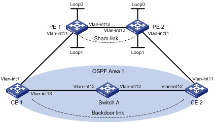
|
设备 |
接口 |
IP地址 |
设备 |
接口 |
IP地址 |
|
CE 1 |
Vlan-int11 |
100.1.1.1/24 |
CE 2 |
Vlan-int11 |
120.1.1.1/24 |
|
|
Vlan-int13 |
20.1.1.1/24 |
|
Vlan-int12 |
30.1.1.2/24 |
|
PE 1 |
Loop0 |
1.1.1.9/32 |
PE 2 |
Loop0 |
2.2.2.9/32 |
|
|
Loop1 |
3.3.3.3/32 |
|
Loop1 |
5.5.5.5/32 |
|
|
Vlan-int11 |
100.1.1.2/24 |
|
Vlan-int11 |
120.1.1.2/24 |
|
|
Vlan-int12 |
10.1.1.1/24 |
|
Vlan-int12 |
10.1.1.2/24 |
|
Switch A |
Vlan-int11 |
20.1.1.2/24 |
|
|
|
|
|
Vlan-int12 |
30.1.1.1/24 |
|
|
|
(1) 配置用户网络上的OSPF
在CE 1、Switch A、CE 2上配置普通OSPF,发布各接口的网段地址。具体配置过程略。
配置完成后,CE 1和CE 2应学到到对端Vlan-interface1接口的OSPF路由。
以CE 1为例:
<CE1> display ip routing-table
Routing Tables: Public
Destinations : 9 Routes : 9
Destination/Mask Proto Pre Cost NextHop Interface
20.1.1.0/24 Direct 0 0 20.1.1.1 Vlan13
20.1.1.1/32 Direct 0 0 127.0.0.1 InLoop0
20.1.1.2/32 Direct 0 0 20.1.1.2 Vlan13
30.1.1.0/24 OSPF 10 3124 20.1.1.2 Vlan13
100.1.1.0/24 Direct 0 0 100.1.1.1 Vlan11
100.1.1.1/32 Direct 0 0 127.0.0.1 InLoop0
120.1.1.0/24 OSPF 10 3125 20.1.1.2 Vlan13
127.0.0.0/8 Direct 0 0 127.0.0.1 InLoop0
127.0.0.1/32 Direct 0 0 127.0.0.1 InLoop0
(2) 在骨干网上配置MPLS L3VPN
# 配置PE 1。
# 配置PE 1的MPLS基本能力和MPLS LDP能力,建立LDP LSP。
<PE1> system-view
[PE1] interface loopback 0
[PE1-LoopBack0] ip address 1.1.1.9 32
[PE1-LoopBack0] quit
[PE1] mpls lsr-id 1.1.1.9
[PE1] mpls
[PE1-mpls] quit
[PE1] mpls ldp
[PE1-mpls-ldp] quit
[PE1] interface vlan-interface 12
[PE1-Vlan-interface12] ip address 10.1.1.1 24
[PE1-Vlan-interface12] mpls
[PE1-Vlan-interface12] mpls ldp
[PE1-Vlan-interface12] quit
# 配置PE 1的MP-IBGP对等体为PE2。
[PE1] bgp 100
[PE1-bgp] peer 2.2.2.9 as-number 100
[PE1-bgp] peer 2.2.2.9 connect-interface loopback 0
[PE1-bgp] ipv4-family vpnv4
[PE1-bgp-af-vpnv4] peer 2.2.2.9 enable
[PE1-bgp-af-vpnv4] quit
[PE1-bgp] quit
# 配置PE 1的OSPF。
[PE1]ospf 1
[PE1-ospf-1]area 0
[PE1-ospf-1-area-0.0.0.0]network 1.1.1.9 0.0.0.0
[PE1-ospf-1-area-0.0.0.0]network 10.1.1.0 0.0.0.255
[PE1-ospf-1-area-0.0.0.0]quit
[PE1-ospf-1]quit
# 配置PE 2的MPLS基本能力和MPLS LDP能力,建立LDP LSP。
<PE2> system-view
[PE2] interface loopback 0
[PE2-LoopBack0] ip address 2.2.2.9 32
[PE2-LoopBack0] quit
[PE2] mpls lsr-id 2.2.2.9
[PE2] mpls
[PE2-mpls] quit
[PE2] mpls ldp
[PE2-mpls-ldp] quit
[PE2] interface vlan-interface 12
[PE2-Vlan-interface12] ip address 10.1.1.2 24
[PE2-Vlan-interface12] mpls
[PE2-Vlan-interface12] mpls ldp
[PE2-Vlan-interface12] quit
# 配置PE 2的MP-IBGP对等体为PE1。
[PE2] bgp 100
[PE2-bgp] peer 1.1.1.9 as-number 100
[PE2-bgp] peer 1.1.1.9 connect-interface loopback 0
[PE2-bgp] ipv4-family vpnv4
[PE2-bgp-af-vpnv4] peer 1.1.1.9 enable
[PE2-bgp-af-vpnv4] quit
[PE2-bgp] quit
# 配置PE 2的OSPF。
[PE2]ospf 1
[PE2-ospf-1]area 0
[PE2-ospf-1-area-0.0.0.0]network 2.2.2.9 0.0.0.0
[PE2-ospf-1-area-0.0.0.0]network 10.1.1.0 0.0.0.255
[PE2-ospf-1-area-0.0.0.0]quit
[PE2-ospf-1]quit
(3) 配置PE接入CE
# 配置PE 1接入CE 1。
[PE1] ip vpn-instance vpn1
[PE1-vpn-instance-vpn1] route-distinguisher 100:1
[PE1-vpn-instance-vpn1] vpn-target 1:1
[PE1-vpn-instance-vpn1] quit
[PE1] interface vlan-interface 11
[PE1-Vlan-interface11] ip binding vpn-instance vpn1
[PE1-Vlan-interface11] ip address 100.1.1.2 24
[PE1-Vlan-interface11] quit
[PE1] ospf 100 vpn-instance vpn1
[PE1-ospf-100] domain-id 10
[PE1-ospf-100] area 1
[PE1-ospf-100-area-0.0.0.1] network 100.1.1.0 0.0.0.255
[PE1-ospf-100-area-0.0.0.1] quit
[PE1-ospf-100] quit
[PE2] bgp 100
[PE1-bgp] ipv4-family vpn-instance vpn1
[PE1-bgp-vpn1] import-route ospf 100
[PE1-bgp-vpn1] import-route direct
[PE1-bgp-vpn1] quit
[PE1-bgp] quit
# 配置PE 2接入CE 2。
[PE2] ip vpn-instance vpn1
[PE2-vpn-instance-vpn1] route-distinguisher 100:2
[PE2-vpn-instance-vpn1] vpn-target 1:1
[PE2-vpn-instance-vpn1] quit
[PE2] interface vlan-interface 11
[PE2-Vlan-interface11] ip binding vpn-instance vpn1
[PE2-Vlan-interface11] ip address 120.1.1.2 24
[PE2-Vlan-interface11] quit
[PE2] ospf 100 vpn-instance vpn1
[PE2-ospf-100] domain-id 10
[PE2-ospf-100] area 1
[PE2-ospf-100-area-0.0.0.1] network 120.1.1.0 0.0.0.255
[PE2-ospf-100-area-0.0.0.1] quit
[PE2-ospf-100] quit
[PE2] bgp 100
[PE2-bgp] ipv4-family vpn-instance vpn1
[PE2-bgp-vpn1] import-route ospf 100
[PE2-bgp-vpn1] import-route direct
[PE2-bgp-vpn1] quit
[PE2-bgp] quit
完成上述配置后,在PE设备上执行display ip routing-table vpn-instance命令,可以看到去往对端CE的路由是通过用户网络的OSPF路由,不是通过骨干网的BGP路由。
以PE 1为例:
[PE1] display ip routing-table vpn-instance vpn1
Routing Tables: vpn1
Destinations : 5 Routes : 5
Destination/Mask Proto Pre Cost NextHop Interface
20.1.1.0/24 OSPF 10 1563 100.1.1.1 Vlan11
30.1.1.0/24 OSPF 10 3125 100.1.1.1 Vlan11
100.1.1.0/24 Direct 0 0 100.1.1.2 Vlan11
100.1.1.2/32 Direct 0 0 127.0.0.1 InLoop0
120.1.1.0/24 OSPF 10 3126 100.1.1.1 Vlan11
(4) 配置Sham-link
# 配置PE 1。
[PE1] interface loopback 1
[PE1-LoopBack1] ip binding vpn-instance vpn1
[PE1-LoopBack1] ip address 3.3.3.3 32
[PE1-LoopBack1] quit
[PE1] ospf 100
[PE1-ospf-100] area 1
[PE1-ospf-100-area-0.0.0.1] sham-link 3.3.3.3 5.5.5.5 cost 10
[PE1-ospf-100-area-0.0.0.1] quit
[PE1-ospf-100] quit
# 配置PE 2。
[PE2] interface loopback 1
[PE2-LoopBack1] ip binding vpn-instance vpn1
[PE2-LoopBack1] ip address 5.5.5.5 32
[PE2-LoopBack1] quit
[PE2] ospf 100
[PE2-ospf-100] area 1
[PE2-ospf-100-area-0.0.0.1] sham-link 5.5.5.5 3.3.3.3 cost 10
[PE2-ospf-100-area-0.0.0.1] quit
[PE2-ospf-100] quit
完成上述配置后,在PE设备上再次执行display ip routing-table vpn-instance命令,可以看到去往对端CE的路由变成了通过骨干网的BGP路由,并且有去往Sham-link目的地址的路由。
以PE 1为例:
[PE1] display ip routing-table vpn-instance vpn1
Routing Tables: vpn1
Destinations : 6 Routes : 6
Destination/Mask Proto Pre Cost NextHop Interface
3.3.3.3/32 Direct 0 0 127.0.0.1 InLoop0
5.5.5.5/32 BGP 255 0 2.2.2.9 NULL0
20.1.1.0/24 OSPF 10 1563 100.1.1.1 Vlan11
100.1.1.0/24 Direct 0 0 100.1.1.2 Vlan11
100.1.1.2/32 Direct 0 0 127.0.0.1 InLoop0
120.1.1.0/24 BGP 255 0 2.2.2.9 NULL0
在CE设备上执行display ip routing-table命令,可以看到去往对端CE的OSPF路由开销变为10(为Sham-link配置的开销),下一跳变为接入PE的Vlan-interface11接口,即去往对端的VPN流量将通过骨干网转发。
以CE 1为例:
[CE1] display ip routing-table
Routing Tables: Public
Destinations : 9 Routes : 9
Destination/Mask Proto Pre Cost NextHop Interface
20.1.1.0/24 Direct 0 0 20.1.1.1 Vlan13
20.1.1.1/32 Direct 0 0 127.0.0.1 InLoop0
20.1.1.2/32 Direct 0 0 20.1.1.2 Vlan13
30.1.1.0/24 OSPF 10 1574 100.1.1.2 Vlan11
100.1.1.0/24 Direct 0 0 100.1.1.1 Vlan11
100.1.1.1/32 Direct 0 0 127.0.0.1 InLoop0
120.1.1.0/24 OSPF 10 12 100.1.1.2 Vlan11
127.0.0.0/8 Direct 0 0 127.0.0.1 InLoop0
127.0.0.1/32 Direct 0 0 127.0.0.1 InLoop0
在PE上执行display ospf sham-link命令可以看到Sham-link的建立情况。
以PE 1为例:
[PE1] display ospf sham-link
OSPF Process 100 with Router ID 100.1.1.2
Sham Link:
Area NeighborId Source-IP Destination-IP State Cost
0.0.0.1 120.1.1.2 3.3.3.3 5.5.5.5 P-2-P 10
执行display ospf sham-link area命令可以看到对端状态为Full。
[PE1] display ospf sham-link area 1
OSPF Process 100 with Router ID 100.1.1.2
Sham-Link: 3.3.3.3 --> 5.5.5.5
Neighbor ID: 120.1.1.2 State: Full
Area: 0.0.0.1
Cost: 10 State: P-2-P Type: Sham
Timers: Hello 10, Dead 40, Retransmit 5, Transmit Delay 1
如图所示,CE 1和CE 2同属于VPN 1,分别接入PE 1和PE 2,并且CE 1和CE 2复用AS号600。
图1-29 BGP的AS号替换组网图
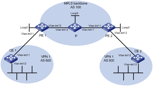
|
设备 |
接口 |
IP地址 |
设备 |
接口 |
IP地址 |
|
CE 1 |
Vlan-int11 |
10.1.1.1/24 |
P |
Loop0 |
2.2.2.9/32 |
|
|
Vlan-int12 |
100.1.1.1/24 |
|
Vlan-int11 |
30.1.1.1/24 |
|
PE 1 |
Loop0 |
1.1.1.9/32 |
|
Vlan-int12 |
20.1.1.2/24 |
|
|
Vlan-int11 |
10.1.1.2/24 |
PE 2 |
Loop0 |
3.3.3.9/32 |
|
|
Vlan-int12 |
20.1.1.1/24 |
|
Vlan-int11 |
30.1.1.2/24 |
|
CE 2 |
Vlan-int12 |
10.2.1.1/24 |
|
Vlan-int12 |
10.2.1.2/24 |
|
|
Vlan-int13 |
200.1.1.1/24 |
|
|
|
(1) 配置基本MPLS L3VPN
· 在MPLS骨干网上配置OSPF,PE和P之间能够学到对方Loopback接口的路由;
· 在MPLS骨干网上配置MPLS基本能力和MPLS LDP,建立LDP LSP;
· PE之间建立MP-IBGP对等体关系,发布VPN-IPv4路由;
· 在PE 2上配置VPN 1的VPN实例,接入CE 2;
· 在PE 1上配置VPN 1的VPN实例,接入CE 1;
· PE 1和CE 1、PE 2和CE 2之间配置BGP,将CE的路由引入PE。
完成上述配置后,在CE 2上执行display ip routing-table命令,可以看到CE 2能够学到CE 1接入PE 1的接口所在网段(10.1.1.0/24)的路由,但没有到达CE 1内部VPN(100.1.1.0/24)的路由。CE 1上也存在同样的现象。
<CE2> display ip routing-table
Routing Tables: Public
Destinations : 8 Routes : 8
Destination/Mask Proto Pre Cost NextHop Interface
10.1.1.0/24 BGP 255 0 10.2.1.2 Vlan11
10.1.1.1/32 BGP 255 0 10.2.1.2 Vlan11
10.2.1.0/24 Direct 0 0 10.2.1.1 Vlan11
10.2.1.1/32 Direct 0 0 127.0.0.1 InLoop0
10.2.1.2/32 Direct 0 0 10.2.1.2 Vlan11
127.0.0.0/8 Direct 0 0 127.0.0.1 InLoop0
127.0.0.1/32 Direct 0 0 127.0.0.1 InLoop0
200.1.1.0/24 Direct 0 0 200.1.1.1 InLoop0
200.1.1.1/32 Direct 0 0 127.0.0.1 InLoop0
在PE上执行display ip routing-table vpn-instance命令,可以看到PE的VPN实例中有到达对端CE内部VPN的路由。
以PE 2为例:
<PE2> display ip routing-table vpn-instance vpn1
Routing Tables: vpn1
Destinations : 7 Routes : 7
Destination/Mask Proto Pre Cost NextHop Interface
10.1.1.0/24 BGP 255 0 1.1.1.9 NULL0
10.1.1.1/32 BGP 255 0 1.1.1.9 NULL0
10.2.1.0/24 Direct 0 0 10.2.1.2 Vlan11
10.2.1.1/32 Direct 0 0 10.2.1.1 Vlan11
10.2.1.2/32 Direct 0 0 127.0.0.1 InLoop0
100.1.1.1/32 BGP 255 0 1.1.1.9 NULL0
200.1.1.1/32 BGP 255 0 10.2.1.1 Vlan11
在PE 2上打开BGP的Update报文调试信息开关,可以看到PE 2发布了去往100.1.1.1/32的路由,AS路径信息为“100 600”。
<PE2> terminal monitor
<PE2> terminal debugging
<PE2> debugging bgp update vpn-instance vpn1 verbose
<PE2> refresh bgp vpn-instance vpn1 all export
*0.4402392 PE2 RM/7/RMDEBUG:
BGP.vpn1: Send UPDATE to 10.2.1.1 for following destinations :
Origin : Incomplete
AS Path : 100 600
Next Hop : 10.2.1.2
100.1.1.1/32,
在CE 2上执行display bgp routing-table peer received-routes命令,可以看到CE 2没有接收100.1.1.1/32的路由。
<CE2> display bgp routing-table peer 10.2.1.2 received-routes
Total Number of Routes: 4
BGP Local router ID is 10.2.1.1
Status codes: * - valid, ^ - VPN best, > - best, d - damped,
h - history, i - internal, s - suppressed, S - Stale
Origin : i - IGP, e - EGP, ? - incomplete
Network NextHop MED LocPrf PrefVal Path/Ogn
*> 10.1.1.0/24 10.2.1.2 0 100?
*> 10.1.1.1/32 10.2.1.2 0 100?
* 10.2.1.0/24 10.2.1.2 0 0 100?
* 10.2.1.1/32 10.2.1.2 0 0 100?
(2) 配置BGP的AS号替换功能
# 在PE 2上配置BGP的AS号替换功能。
<PE2> system-view
[PE2] bgp 100
[PE2-bgp] ipv4-family vpn-instance vpn1
[PE2-bgp-vpn1] peer 10.2.1.1 substitute-as
[PE2-bgp-vpn1] quit
[PE2-bgp] quit
可以看到PE 2向CE2发布的路由中,100.1.1.1/32的AS路径信息由“100 600”变为“100 100”:
*0.13498737 PE2 RM/7/RMDEBUG:
BGP.vpn1: Send UPDATE to 10.2.1.1 for following destinations :
Origin : Incomplete
AS Path : 100 100
Next Hop : 10.2.1.2
100.1.1.1/32
再次查看CE 2接收的路由信息和路由表:
<CE2> display bgp routing-table peer 10.2.1.2 received-routes
Total Number of Routes: 5
BGP Local router ID is 10.2.1.1
Status codes: * - valid, ^ - VPN best, > - best, d - damped,
h - history, i - internal, s - suppressed, S - Stale
Origin : i - IGP, e - EGP, ? - incomplete
Network NextHop MED LocPrf PrefVal Path/Ogn
*> 10.1.1.0/24 10.2.1.2 0 100?
*> 10.1.1.1/32 10.2.1.2 0 100?
* 10.2.1.0/24 10.2.1.2 0 0 100?
* 10.2.1.1/32 10.2.1.2 0 0 100?
*> 100.1.1.1/32 10.2.1.2 0 100 100?
<CE2> display ip routing-table
Routing Tables: Public
Destinations : 9 Routes : 9
Destination/Mask Proto Pre Cost NextHop Interface
10.1.1.0/24 BGP 255 0 10.2.1.2 Vlan12
10.1.1.1/32 BGP 255 0 10.2.1.2 Vlan12
10.2.1.0/24 Direct 0 0 10.2.1.1 Vlan12
10.2.1.1/32 Direct 0 0 127.0.0.1 InLoop0
10.2.1.2/32 Direct 0 0 10.2.1.2 Vlan12
100.1.1.1/32 BGP 255 0 10.2.1.2 Vlan12
127.0.0.0/8 Direct 0 0 127.0.0.1 InLoop0
127.0.0.1/32 Direct 0 0 127.0.0.1 InLoop0
200.1.1.1/32 Direct 0 0 127.0.0.1 InLoop0
在PE 1上也配置BGP的AS号替换功能后,CE 1和CE 2的VLAN接口能够相互Ping通。
<CE1> ping –a 100.1.1.1 200.1.1.1
PING 200.1.1.1: 56 data bytes, press CTRL_C to break
Reply from 200.1.1.1: bytes=56 Sequence=1 ttl=253 time=109 ms
Reply from 200.1.1.1: bytes=56 Sequence=2 ttl=253 time=67 ms
Reply from 200.1.1.1: bytes=56 Sequence=3 ttl=253 time=66 ms
Reply from 200.1.1.1: bytes=56 Sequence=4 ttl=253 time=85 ms
Reply from 200.1.1.1: bytes=56 Sequence=5 ttl=253 time=70 ms
--- 200.1.1.1 ping statistics ---
5 packet(s) transmitted
5 packet(s) received
0.00% packet loss
round-trip min/avg/max = 66/79/109 ms
· CE 1、CE 2和CE 3同属于VPN 1,分别接入PE 1、PE 2和PE 3。
· CE 1和CE 2位于同一个站点。
· CE 1、CE 2和CE 3复用AS号600。
· 为了避免路由丢失,在PE上配置AS号替换;为了避免路由在CE 1和CE 2之间产生环路,在PE 1和PE 2上分别通过路由策略为从CE 1和CE 2学习到的路由添加SoO属性。
图1-30 BGP的AS号替换和SoO属性组网图
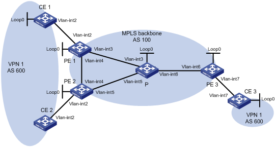
|
设备 |
接口 |
IP地址 |
设备 |
接口 |
IP地址 |
|
CE 1 |
Loop0 |
100.1.1.1/32 |
CE 3 |
Loop0 |
200.1.1.1/32 |
|
|
Vlan-int2 |
10.1.1.1/24 |
|
Vlan-int7 |
10.3.1.1/24 |
|
CE 2 |
Vlan-int2 |
10.2.1.1/24 |
PE 2 |
Loop0 |
2.2.2.9/32 |
|
PE 1 |
Loop0 |
1.1.1.9/32 |
|
Vlan-int2 |
10.2.1.2/24 |
|
|
Vlan-int2 |
10.1.1.2/24 |
|
Vlan-int4 |
20.1.1.2/24 |
|
|
Vlan-int3 |
30.1.1.1/24 |
|
Vlan-int5 |
40.1.1.1/24 |
|
|
Vlan-int4 |
20.1.1.1/24 |
P |
Loop0 |
3.3.3.9/32 |
|
PE 3 |
Loop0 |
4.4.4.9/32 |
|
Vlan-int3 |
30.1.1.2/24 |
|
|
Vlan-int6 |
50.1.1.2/24 |
|
Vlan-int5 |
40.1.1.2/24 |
|
|
Vlan-int7 |
10.3.1.2/24 |
|
Vlan-int6 |
50.1.1.1/24 |
(1) 配置基本MPLS L3VPN
· 在MPLS骨干网上配置OSPF,PE和P之间能够学到对方Loopback接口的路由;(配置过程略)
· 在MPLS骨干网上配置MPLS基本能力和MPLS LDP,建立LDP LSP;(配置过程略)
· PE之间建立MP-IBGP对等体关系,发布VPN-IPv4路由;(配置过程略)
· 在PE 1上配置VPN 1的VPN实例,接入CE 1;(配置过程略)
· 在PE 2上配置VPN 1的VPN实例,接入CE 2;(配置过程略)
· 在PE 3上配置VPN 1的VPN实例,接入CE 3;(配置过程略)
· PE 1和CE 1、PE 2和CE 2、PE 3和CE 3之间配置BGP,将CE的路由引入PE。(配置过程略)
(2) 配置BGP的AS号替换功能
# 在PE 1、PE 2和PE 3上配置BGP的AS号替换功能,具体配置参见“1.10.11 配置BGP的AS号替换”。
# 查看CE 2接收的路由信息,可以看到CE 1发来的路由100.1.1.1/32。可见,由于CE 1和CE 2位于同一站点,造成了路由环路。
<CE2> display bgp routing-table peer 10.2.1.2 received-routes
Total Number of Routes: 8
BGP Local router ID is 10.2.1.1
Status codes: * - valid, ^ - VPN best, > - best, d - damped,
h - history, i - internal, s - suppressed, S - Stale
Origin : i - IGP, e - EGP, ? - incomplete
Network NextHop MED LocPrf PrefVal Path/Ogn
*> 10.1.1.0/24 10.2.1.2 0 100?
*> 10.1.1.1/32 10.2.1.2 0 100?
* 10.2.1.0/24 10.2.1.2 0 0 100?
* 10.2.1.1/32 10.2.1.2 0 0 100?
* 10.3.1.0/24 10.2.1.2 0 100?
* 10.3.1.1/32 10.2.1.2 0 100?
*> 100.1.1.1/32 10.2.1.2 0 100 100?
*> 200.1.1.1/32 10.2.1.2 0 100 100?
(3) 配置BGP的SoO属性
# 在PE 1上配置路由策略soo,为路由添加SoO属性1:100。
<PE1> system-view
[PE1] route-policy soo permit node 10
[PE1-route-policy] apply extcommunity soo 1:100 additive
[PE1-route-policy] quit
# 在PE 1上为从CE 1学习的路由应用路由策略soo。
[PE1] bgp 100
[PE1-bgp] ipv4-family vpn-instance vpn1
[PE1-bgp-vpn1] peer 10.1.1.1 route-policy soo import
[PE1-bgp-vpn1] quit
[PE1-bgp] quit
# 在PE 2上配置路由策略soo,为路由添加SoO属性1:100。
<PE2> system-view
[PE2] route-policy soo permit node 10
[PE2-route-policy] apply extcommunity soo 1:100 additive
[PE2-route-policy] quit
# 在PE 2上为从CE 2学习的路由应用路由策略soo。
[PE2] bgp 100
[PE2-bgp] ipv4-family vpn-instance vpn1
[PE2-bgp-vpn1] peer 10.2.1.1 route-policy soo import
[PE2-bgp-vpn1] quit
[PE2-bgp] quit
# 由于配置的SoO属性相同,PE 2不会将CE 1发过来的路由发布给CE 2。查看CE 2路由表,不会再看到100.1.1.1/32路由。
<CE2> display ip routing-table
Routing Tables: Public
Destinations : 9 Routes : 9
Destination/Mask Proto Pre Cost NextHop Interface
10.1.1.0/24 BGP 255 0 10.2.1.2 Vlan2
10.1.1.1/32 BGP 255 0 10.2.1.2 Vlan2
10.2.1.0/24 Direct 0 0 10.2.1.1 Vlan2
10.2.1.1/32 Direct 0 0 127.0.0.1 InLoop0
10.3.1.0/24 BGP 255 0 10.2.1.2 Vlan2
10.3.1.1/32 BGP 255 0 10.2.1.2 Vlan2
127.0.0.0/8 Direct 0 0 127.0.0.1 InLoop0
127.0.0.1/32 Direct 0 0 127.0.0.1 InLoop0
200.1.1.1/32 BGP 255 0 10.2.1.2 Vlan2
MPLS L3VPN应用于IPv4组网环境,利用BGP在服务提供商骨干网上发布VPN的IPv4路由,利用MPLS在服务提供商骨干网上转发VPN的IPv4报文。
IPv6 MPLS L3VPN的原理与MPLS L3VPN相同,所不同的是IPv6 MPLS L3VPN利用BGP在服务提供商骨干网上发布VPN的IPv6路由,利用MPLS在服务提供商骨干网上转发VPN的IPv6报文。
IPv6 MPLS L3VPN的典型组网环境如图2-1所示。目前,IPv6 MPLS L3VPN组网中服务提供商骨干网应为IPv4网络。VPN内部及CE和PE之间运行IPv6协议,骨干网中PE和P设备之间运行IPv4协议。PE需要同时支持IPv4和IPv6协议,连接CE的接口上使用IPv6协议,连接骨干网的接口上使用IPv4协议。
图2-1 IPv6 MPLS L3VPN应用组网图
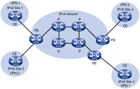
图2-2 IPv6 MPLS L3VPN报文转发示意图
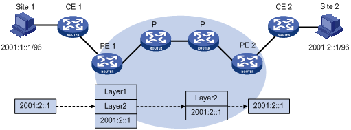
如图2-2所示,IPv6 MPLS L3VPN的报文转发过程为:
(1) Site 1发出一个目的地址为2001:2::1的IPv6报文,由CE 1将报文发送至PE 1。
(2) PE 1根据报文到达的接口及目的地址查找VPN实例的路由表项,匹配后将报文转发出去,同时打上内层和外层两个标签。
(3) MPLS网络利用报文的外层标签,将报文传送到PE 2。(报文在到达PE 2前一跳时已经被剥离外层标签,到达PE 2时仅含内层标签)
(4) PE 2根据内层标签和目的地址查找VPN实例的路由表项,确定报文的出接口,将报文转发至CE 2。
(5) CE 2根据正常的IPv6转发过程将报文传送到目的地。
VPN路由信息的发布过程包括三部分:本地CE到入口PE、入口PE到出口PE、出口PE到远端CE。完成这三部分后,本地CE与远端CE之间将建立可达路由,VPN私网路由信息能够在骨干网上发布。
CE与直接相连的PE建立邻接关系后,把本站点的VPN IPv6路由发布给PE。
CE与PE之间可以使用IPv6静态路由、RIPng、OSPFv3、IPv6 IS-IS、EBGP路由协议。无论使用哪种路由协议,CE发布给PE的都是标准的IPv6路由。
PE从CE学到VPN的IPv6路由信息后,为这些标准IPv6路由增加RD和VPN Target属性,形成VPN-IPv6路由,存放到为CE创建的VPN实例的路由表中,并触发MPLS为其分配私网标签。
入口PE通过MP-BGP把VPN-IPv6路由发布给出口PE。出口PE根据VPN-IPv6路由的Export Target属性与自己维护的VPN实例的Import Target属性,决定是否将该路由加入到VPN实例的路由表。
PE之间通过IGP来保证内部的连通性。
与本地CE到入口PE的路由信息交换相同,远端CE有多种方式可以从出口PE学习VPN路由,包括IPv6静态路由、RIPng、OSPFv3、IPv6 IS-IS、EBGP路由协议。
目前,IPv6 MPLS L3VPN支持如下组网方案及功能:
· 基本的VPN组网方案
· 跨域VPN-OptionA
· 跨域VPN-OptionC
· 运营商的运营商
表2-1 IPv6 MPLS L3VPN配置任务简介
|
配置任务 |
详细配置 |
说明 |
|
配置基本IPv6 MPLS L3VPN |
完成基本IPv6 MPLS L3VPN配置后,即可实现通过MPLS技术构建简单的IPv6 VPN网络 如果部署一些特殊的IPv6 MPLS L3VPN组网方案,例如跨域VPN,除了配置基本IPv6 MPLS L3VPN外,还需要根据相应章节进行其他的配置 |
|
|
配置IPv6跨域VPN |
配置IPv6 MPLS L3VPN的关键在于管理VPN私网路由在MPLS骨干网上的发布,包括PE-CE间的路由发布管理以及PE-PE间的路由发布管理。
表2-2 基本IPv6 MPLS L3VPN配置任务简介
|
配置任务 |
说明 |
详细配置 |
|
|
配置VPN实例 |
创建VPN实例 |
必选 |
|
|
配置VPN实例与接口关联 |
必选 |
||
|
配置VPN实例的路由相关属性 |
可选 |
||
|
配置VPN实例的隧道策略 |
可选 |
||
|
配置LDP实例 |
可选 |
||
|
配置PE-CE间的路由交换 |
必选 |
||
|
配置PE-PE间的路由交换 |
必选 |
||
|
配置BGP-VPNv6子地址族下的路由特性 |
可选 |
||
在配置基本IPv6 MPLS L3VPN之前,需完成以下任务:
· 对MPLS骨干网(PE、P)配置IGP,实现骨干网的IP连通性
· 对MPLS骨干网(PE、P)配置MPLS基本能力
· 对MPLS骨干网(PE、P)配置MPLS LDP,建立LDP LSP
VPN实例不仅可以隔离VPN私网路由与公网路由,还可以隔离不同VPN实例的路由,这一特点使得VPN实例的使用不限于MPLS L3VPN。
配置VPN实例的操作是在PE或MCE设备上进行的。
VPN实例在实现中与Site关联。VPN实例不是直接对应于VPN,一个VPN实例综合了和它所对应Site的VPN成员关系和路由规则。
表2-3 创建VPN实例
|
操作 |
命令 |
说明 |
|
进入系统视图 |
system-view |
- |
|
创建VPN实例,并进入VPN实例视图 |
ip vpn-instance vpn-instance-name |
必选 |
|
配置VPN实例的RD |
route-distinguisher route-distinguisher |
必选 一个VPN实例只有配置了RD后才生效 |
|
配置VPN实例的描述信息 |
description text |
可选 描述信息用于描述VPN实例,可以用来记录VPN实例与某个VPN的关系等信息 |
VPN实例配置完成后,还需要与连接CE的接口进行关联。支持MPLS LDP能力的接口类型都可以与VPN实例相关联。具体接口类型请参见“MPLS配置指导”中的“MPLS基础”。
表2-4 配置VPN实例与接口关联
|
操作 |
命令 |
说明 |
|
进入系统视图 |
system-view |
- |
|
进入要关联接口的接口视图 |
interface interface-type interface-number |
- |
|
将当前接口与VPN实例关联 |
ip binding vpn-instance vpn-instance-name |
必选 缺省情况下,接口不关联任何VPN实例 |
![]()
执行ip binding vpn-instance命令将删除接口上已经配置的IPv6地址,因此需要重新配置接口的IPv6地址。
VPN路由的发布控制过程如下:
· 当从CE学习到的一条VPN路由引入BGP时,BGP为它关联一个VPN Target扩展团体属性列表,通常这个列表是与CE相关联的VPN实例的输出路由属性列表。
· VPN实例根据VPN Target中import-extcommunity确定可被接受并引入此VPN实例的路由。
· VPN实例根据VPN Target中的export-extcommunity对向外发布的路由进行VPN Target属性的修改。
表2-5 配置VPN实例的路由相关属性
|
操作 |
命令 |
说明 |
|
进入系统视图 |
system-view |
- |
|
进入VPN实例视图 |
ip vpn-instance vpn-instance-name |
- |
|
进入IPv6 VPN视图 |
ipv6-family |
可选 |
|
配置VPN Target |
vpn-target vpn-target&<1-8> [ both | export-extcommunity | import-extcommunity ] |
必选 |
|
配置支持的最大路由数 |
routing-table limit number { warn-threshold | simply-alert } |
可选 |
|
应用入方向路由策略 |
import route-policy route-policy |
可选 缺省情况下,接收所有VPN Target属性匹配的路由 |
|
应用出方向路由策略 |
export route-policy route-policy |
可选 缺省情况下,不对发布的路由进行过滤 |
![]()
· VPN实例视图下配置的路由相关属性既可以用于IPv4 VPN,也可以用于IPv6 VPN。
· 既可以在VPN实例视图下,也可以在IPv6 VPN视图下,配置IPv6 VPN的路由相关属性。如果同时在两个视图下配置了路由相关属性,则IPv6 VPN采用IPv6 VPN视图下配置的路由相关属性。
· 命令vpn-target最多可以配置8个VPN Target;一个VPN实例最多可以配置64个VPN Target。
· 可以配置一个VPN实例支持的最大路由数,以防止PE路由器的入接口有过多的路由。
· 为VPN实例配置路由策略之前必须已经创建了路由策略,否则无法对接收和发布的路由进行过滤。
在网络中存在多条、多种类型的隧道时,可以通过配置隧道策略对选择的隧道种类和隧道数目进行限制。
通过tunnel select-seq命令,可以配置隧道的优先级顺序和负载分担条数。
通过preferred-path命令可以配置优选路径,每条优选路径对应一个隧道接口,指定通过哪个隧道接口转发流量。
应用隧道策略后,隧道的选择方式为:
(1) 从编号最小的优选路径开始匹配,如果对端PE地址和任何优选路径的隧道目的地址都不同,则根据tunnel select-seq命令配置的隧道优先级顺序和负载分担条数选择隧道。如果没有配置tunnel select-seq命令,则根据缺省的隧道策略选择隧道,即按照LSP隧道->CR-LSP隧道的优先级顺序选择隧道,负载分担条数为1。
(2) 如果对端PE地址和某条优选路径的隧道目的地址相同,则匹配成功。此优选路径指定的隧道可用时,不再匹配后续的隧道策略规则,使用该优选路径指定的隧道接口转发流量。
(3) 匹配的优选路径指定的隧道不可用时(例如,隧道接口down、隧道下配置的ACL规则不允许转发该流量等原因导致隧道不可用),如果该优选路径中没有指定disable-fallback参数,则继续匹配后续的隧道策略规则;如果该优选路径中指定了disable-fallback参数,则不再匹配后续的隧道策略规则,隧道查找失败。
表2-6 配置VPN实例的隧道策略
|
操作 |
命令 |
说明 |
|
进入系统视图 |
system-view |
- |
|
创建隧道策略,并进入隧道策略视图 |
tunnel-policy tunnel-policy-name |
必选 |
|
配置通过隧道接口转发报文的优选路径 |
preferred-path number interface tunnel tunnel-number [ disable-fallback ] |
可选 缺省情况下,不存在任何优选路径 |
|
配置隧道的优先级顺序和负载分担条数 |
tunnel select-seq { cr-lsp | lsp } * load-balance-number number |
可选 缺省情况下,按照LSP隧道-> CR-LSP隧道的优先级顺序选择隧道,负载分担条数为1 |
|
退回系统视图 |
quit |
- |
|
进入VPN实例视图 |
ip vpn-instance vpn-instance-name |
必选 |
|
进入IPv6 VPN视图 |
ipv6-family |
可选 |
|
配置VPN实例的隧道策略 |
tnl-policy tunnel-policy-name |
必选 缺省情况下,按照LSP隧道-> CR-LSP隧道的优先级顺序选择隧道,负载分担条数为1 |
![]()
· 配置的隧道类型不止一种,且负载分担的条数多于单个类型包含的隧道个数时,会使用不同类型的隧道一起进行负载分担。
· 一个隧道策略下最多可以配置64条优选路径。不同优选路径对应的隧道接口的目的地址可以相同。隧道接口的隧道类型必须为MPLS TE。
· 在配置隧道优先级顺序时,隧道类型越靠近关键字select-seq的,其优先级越高。例如:如果配置了命令tunnel select-seq lsp cr-lsp load-balance-number 1,在没有LSP的情况下,VPN将使用CR-LSP隧道,当LSP建立后,VPN将选用LSP。
· VPN实例视图下配置的隧道策略既可以用于IPv4 VPN,也可以用于IPv6 VPN。
· 既可以在VPN实例视图下,也可以在IPv6 VPN视图下,配置IPv6 VPN的隧道策略。如果同时在两个视图下配置了隧道策略,则IPv6 VPN采用IPv6 VPN视图下配置的隧道策略。
· 为VPN实例配置隧道策略之前必须先创建隧道策略,否则将采用缺省策略,即按照LSP隧道-> CR-LSP隧道的优先级顺序选择隧道,负载分担条数为1。
LDP实例应用于运营商的运营商(Carriers’ carriers)组网模型中。
本配置任务用来使能VPN实例的LDP能力,创建LDP实例,并在MPLS-LDP-VPN实例视图下为VPN实例配置LDP参数。
LDP实例的配置方法,请参见“1.3.3 5. 配置LDP实例”。
PE-CE间路由交换可以使用IPv6静态路由、RIPng、OSPFv3、IPv6 IS-IS和EBGP路由协议。根据实际组网情况选择一种进行配置即可。
在配置PE-CE间路由交换之前,需要先完成以下任务:
· 在CE上配置连接PE接口的IPv6地址
· 在PE上配置连接CE接口的IPv6地址
表2-7 配置PE-CE间使用IPv6静态路由
|
操作 |
命令 |
说明 |
|
进入系统视图 |
system-view |
- |
|
为指定VPN实例配置IPv6静态路由 |
ipv6 route-static ipv6-address prefix-length { interface-type interface-number [ next-hop-address ] | next-hop-address | vpn-instance d-vpn-instance-name nexthop-address } [ preference preference-value ] |
二者必选其一 该配置在PE上进行,CE上的配置方法与普通IPv6静态路由相同 |
|
ipv6 route-static vpn-instance s-vpn-instance-name&<1-6> ipv6-address prefix-length { interface-type interface-number [ next-hop-address ] | nexthop-address [ public ] | vpn-instance d-vpn-instance-name nexthop-address } [ preference preference-value ] |
![]()
有关IPv6静态路由的配置请参见“三层技术-IP路由配置指导”中的“IPv6静态路由”。
一个RIPng进程只能属于一个VPN实例。如果在启动RIPng进程时不绑定到VPN实例,则该进程属于公网进程。
表2-8 配置PE-CE间使用RIPng
|
操作 |
命令 |
说明 |
|
进入系统视图 |
system-view |
- |
|
创建PE-CE间的RIPng实例,并进入RIPng视图 |
ripng [ process-id ] vpn-instance vpn-instance-name |
必选 该配置在PE上进行,CE上配置普通RIPng即可 |
|
退回系统视图 |
quit |
- |
|
进入接口视图 |
interface interface-type interface-number |
- |
|
在指定的网络接口上使能RIPng |
ripng process-id enable |
必选 缺省情况下,接口禁用RIPng |
![]()
有关RIPng的介绍和详细配置,请参见“三层技术-IP路由配置指导”中的“RIPng”。
一个OSPFv3进程只能属于一个VPN实例。如果在启动OSPFv3进程时不绑定到VPN实例,则该进程属于公网进程。
表2-9 配置PE-CE间使用OSPFv3
|
操作 |
命令 |
说明 |
|
进入系统视图 |
system-view |
- |
|
创建PE-CE间的OSPFv3实例,并进入OSPFv3视图 |
ospfv3 [ process-id ] vpn-instance vpn-instance-name |
必选 该配置在PE上进行,CE上配置普通OSPFv3即可 |
|
配置Router ID |
router-id router-id |
必选 |
|
退回系统视图 |
quit |
- |
|
进入接口视图 |
interface interface-type interface-number |
- |
|
在接口上使能OSPFv3 |
ospfv3 process-id area area-id [ instance instance-id ] |
必选 缺省情况下,接口上没有使能OSPFv3 该配置在PE上进行 |
![]()
有关OSPFv3的介绍和详细配置,请参见“三层技术-IP路由配置指导”中的“OSPFv3”。
一个IPv6 IS-IS进程只能属于一个VPN实例。如果在启动IPv6 IS-IS进程时不绑定到VPN实例,则该进程属于公网进程。
表2-10 配置PE-CE间使用IPv6 IS-IS
|
操作 |
命令 |
说明 |
|
进入系统视图 |
system-view |
- |
|
创建PE-CE间的IPv6 IS-IS实例,并进入IS-IS视图 |
isis [ process-id ] vpn-instance vpn-instance-name |
必选 该配置在PE上进行,CE上配置普通IPv6 IS-IS即可 |
|
配置网络实体名称 |
network-entity net |
必选 缺省情况下,没有配置网络实体名称 |
|
使能IS-IS进程的IPv6能力 |
ipv6 enable |
必选 缺省情况下,没有使能IS-IS路由进程的IPv6能力 |
|
退回系统视图 |
quit |
- |
|
进入接口视图 |
interface interface-type interface-number |
- |
|
使能接口IS-IS路由进程的IPv6能力,并指定要关联的IS-IS进程号 |
isis ipv6 enable [ process-id ] |
必选 缺省情况下,接口上没有使能IS-IS路由进程的IPv6能力 |
![]()
有关IPv6 IS-IS的介绍和详细配置,请参见“三层技术-IP路由配置指导”中的“IPv6 IS-IS”。
(1) PE上的配置
表2-11 PE上的配置
|
操作 |
命令 |
说明 |
|
进入系统视图 |
system-view |
- |
|
进入BGP视图 |
bgp as-number |
- |
|
进入IPv6 BGP-VPN实例视图 |
ipv6-family vpn-instance vpn-instance-name |
必选 |
|
将CE配置为VPN私网EBGP对等体 |
peer ipv6-address as-number as-number |
必选 |
|
引入本端CE路由 |
import-route protocol [ process-id ] [ med med-value | route-policy route-policy-name ] * |
必选 PE需要将到本端CE的路由引入VPN路由表中,以发布给对端PE |
|
配置对发布的路由信息进行过滤 |
filter-policy { acl6-number | ipv6-prefix ipv6-prefix-name } export [ direct | isisv6 process-id | ripng process-id | static ] |
可选 缺省情况下,不对发布的路由信息进行过滤 |
|
配置对接收的路由信息进行过滤 |
filter-policy { acl6-number | ipv6-prefix ipv6-prefix-name } import |
可选 缺省情况下,不对接收的路由信息进行过滤 |
(2) CE上的配置
表2-12 CE上的配置
|
操作 |
命令 |
说明 |
|
进入系统视图 |
system-view |
- |
|
进入BGP视图 |
bgp as-number |
- |
|
进入IPv6 BGP子地址族视图 |
ipv6-family |
必选 |
|
将PE配置为EBGP对等体 |
peer ipv6-address as-number as-number |
必选 |
|
配置路由引入 |
import-route protocol [ process-id ] [ med med-value | route-policy route-policy-name ] * |
可选 CE需要将自己所能到达的VPN网段地址发布给接入的PE,通过PE发布给对端CE |
![]()
· 配置IPv6 BGP-VPN实例后,VPN实例中的BGP路由交换与普通的BGP相同。
· IPv6 BGP-VPN实例视图下的配置命令与IPv6 BGP子地址族视图下的配置命令相同。上文只列举了部分配置命令,更多的配置命令请参见“三层技术-IP路由配置指导”中的“IPv6 BGP”。
表2-13 配置PE-PE间的路由交换
|
操作 |
命令 |
说明 |
|
|
进入系统视图 |
system-view |
- |
|
|
进入BGP视图 |
bgp as-number |
必选 |
|
|
将对端PE配置为对等体 |
peer ip-address as-number as-number |
必选 |
|
|
指定路由更新报文的源接口 |
peer { group-name | ip-address } connect-interface interface-type interface-number |
必选 缺省情况下,BGP使用最佳路由更新报文的源接口 |
|
|
进入BGP-VPNv6子地址族视图 |
ipv6-family vpnv6 |
必选 |
|
|
使能对等体交换BGP-VPNv6路由信息 |
peer ip-address enable |
必选 缺省情况下,BGP对等体之间只能交换IPv4路由信息 |
|
BGP-VPNv6子地址族下的很多路由特性都与BGP IPv6单播路由的特性相同。这些特性根据组网的需求来决定是否选择。
表2-14 配置BGP-VPNv6子地址族的路由特性
|
操作 |
命令 |
说明 |
|
进入系统视图 |
system-view |
- |
|
进入BGP视图 |
bgp as-number |
- |
|
将对端PE配置为对等体 |
peer ip-address as-number as-number |
必选 |
|
指定建立TCP连接的接口 |
peer ip-address connect-interface interface-type interface-number |
必选 |
|
进入BGP-VPNv6子地址族视图 |
ipv6-family vpnv6 |
- |
|
配置本地优先级的缺省值 |
default local-preference value |
可选 缺省情况下,本地优先级的值为100 |
|
配置系统MED的缺省值 |
default med med-value |
可选 缺省情况下,系统MED的缺省值为0 |
|
配置对发布的路由信息进行过滤 |
filter-policy { acl6-number | ipv6-prefix ipv6-prefix-name } export [ direct | isisv6 process-id | ripng process-id | static ] |
可选 缺省情况下,不对发布的路由信息进行过滤 |
|
配置对接收的路由信息进行过滤 |
filter-policy { acl6-number | ipv6-prefix ipv6-prefix-name } import |
可选 缺省情况下,不对接收的路由信息进行过滤 |
|
配置为指定对等体应用过滤策略 |
peer ip-address filter-policy acl6-number { export | import } |
可选 缺省情况下,没有为对等体应用过滤策略 |
|
为指定对等体应用基于IPv6地址前缀列表的路由过滤策略 |
peer ip-address ipv6-prefix prefix-name { export | import } |
可选 缺省情况下,对等体上不应用基于IPv6地址前缀列表的路由过滤策略 |
|
为从对等体接收的路由分配首选值 |
peer ip-address preferred-value value |
可选 缺省情况下,从对等体接收的路由的首选值为0 |
|
配置发送BGP更新报文时不携带私有自治系统号 |
peer ip-address public-as-only |
可选 缺省情况下,发送BGP更新报文时,携带私有自治系统号 |
|
为指定对等体配置路由策略 |
peer ip-address route-policy route-policy-name { export | import } |
可选 缺省情况下,对等体没有应用路由策略 |
|
对接收到的BGP-VPNv6子地址族的BGP路由使能VPN-Target过滤功能 |
policy vpn-target |
可选 缺省情况下,对接收到的BGP-VPNv6子地址族的BGP路由使能VPN-Target过滤功能 |
|
配置将本机作为路由反射器,并将对等体作为路由反射器的客户 |
peer ip-address reflect-client |
可选 缺省情况下,没有配置路由反射器及其客户 |
|
允许客户到客户的路由反射 |
reflect between-clients |
可选 缺省情况下,允许客户到客户的路由反射 |
|
为路由反射器配置群ID |
reflector cluster-id { cluster-id | ip-address } |
可选 缺省情况下,每个路由反射器都使用自己的Router ID作为群ID 如果一个群中配置了多个路由反射器,请使用本命令为所有的路由反射器配置相同的群ID,以避免产生路由环路 |
|
创建路由反射器的反射策略 |
rr-filter extended-community-list-number |
可选 缺省情况下,路由反射器不会对反射的路由进行过滤 执行本命令后,只有与本命令配置的扩展团体属性号匹配的IBGP路由才会被反射 通过在不同的路由反射器上配置不同的反射策略,可以实现路由反射器之间的负载分担 |
![]()
有关IPv6 BGP的路由特性请参见“三层技术-IP路由配置指导”中的“IPv6 BGP”。
如果承载IPv6 VPN路由的MPLS骨干网跨越多个AS,就需要配置跨域VPN。
跨域VPN有三种解决方案,具体介绍请参见“1.1.6 跨域VPN”。目前,IPv6 MPLS L3VPN只支持VPN-OptionA和VPN-OptionC。
在配置跨域VPN之前,需完成以下任务:
· 为各AS的MPLS骨干网分别配置IGP,实现同一AS内骨干网的IP连通性
· 为各AS的MPLS骨干网分别配置MPLS基本能力
· 为各AS的MPLS骨干网分别配置MPLS LDP,建立LDP LSP
![]()
请根据实际应用的IPv6跨域VPN方式,选择下述配置任务中的对应项。
IPv6跨域VPN-OptionA的实现比较简单,当PE上的VPN数量及VPN路由数量都比较少时可以采用这种方案。
IPv6跨域VPN-OptionA的配置可以描述为:
· 对各AS分别进行基本IPv6 MPLS L3VPN配置。
· 对于ASBR-PE,将对端ASBR-PE看作自己的CE配置即可。即:IPv6跨域VPN-OptionA方式需要在PE和ASBR-PE上分别配置IPv6 VPN实例,前者用于接入CE,后者用于接入对端ASBR-PE。
具体配置方法,请参见“2.3 配置基本IPv6 MPLS L3VPN”。
![]()
在IPv6跨域VPN-OptionA方式中,对于同一个IPv6 VPN,同一AS内的ASBR-PE和PE上配置的VPN Target应能匹配,即VPN Target的配置应能保证PE(或ASBR-PE)发送的VPN路由能够被ASBR-PE(或PE)接受;不同AS的PE上配置的VPN Target则不需要匹配。
同一AS内的PE和ASBR-PE之间建立普通的IBGP对等体关系,不同AS的PE之间建立MP-EBGP对等体关系。
同一AS内的PE和ASBR-PE之间应能够交换带标签的路由。
表2-15 配置PE
|
操作 |
命令 |
说明 |
|
进入系统视图 |
system-view |
- |
|
进入BGP视图 |
bgp as-number |
- |
|
配置本AS的ASBR-PE为IBGP对等体 |
peer { group-name | ip-address } as-number as-number |
必选 |
|
配置与本AS的ASBR-PE之间能够交换带标签的路由 |
peer { group-name | ip-address } label-route-capability |
必选 缺省情况下,不向IPv4对等体/对等体组发送标签路由 |
|
将另一AS的PE配置为EBGP对等体 |
peer { group-name | ip-address } as-number as-number |
必选 |
|
进入BGP-VPNv6子地址族视图 |
ipv6-family vpnv6 |
- |
|
使能EBGP对等体交换BGP-VPNv6路由信息 |
peer ip-address enable |
必选 |
在跨域VPN-OptionC方式中,需要建立一条跨域的VPN LSP,相关PE、ASBR之间发布公网路由时携带MPLS标签信息。此跨域VPN LSP的建立同IPv4 MPLS VPN相同,配置方式参见“1.4.4 配置跨域VPN-OptionC”。
配置在ASBR-PE上应用路由策略:
· 对于从本AS的PE接收的路由,在向对端ASBR-PE发布时,分配MPLS标签;
· 对于向本AS的PE发布的路由,如果是带标签的路由,为其分配新的MPLS标签。
IPv6跨域VPN路由策略的配置与IPv4 MPLS VPN相同,配置方式参见“1.4.4 配置跨域VPN-OptionC”。
当BGP配置变化后,可以通过软复位或复位BGP连接使新的配置生效。软复位需要BGP对等体具备路由刷新能力(支持ROUTE-REFRESH消息)。
![]()
软复位BGP连接是指在不断开BGP邻居关系的情况下,更新BGP路由信息;复位BGP连接是指断开并重新建立BGP邻居关系的情况下,更新BGP路由信息。
请在用户视图下进行下列操作。
表2-16 复位BGP连接
|
操作 |
命令 |
|
软复位指定VPN实例的IPv6 BGP连接 |
refresh bgp ipv6 vpn-instance vpn-instance-name { ipv6-address | all | external } { export | import } |
|
软复位BGP的VPNv6连接 |
refresh bgp vpnv6 { ip-address | all | external | internal } { export | import } |
|
复位指定VPN实例的IPv6 BGP连接 |
reset bgp ipv6 vpn-instance vpn-instance-name { as-number | ipv6-address | all | external } |
|
复位BGP的VPNv6连接 |
reset bgp vpnv6 { as-number | ip-address | all | external | internal } |
在完成上述配置后,在任意视图下执行display命令可以显示配置后IPv6 MPLS L3VPN的运行情况,通过查看显示信息验证配置的效果。
表2-17 显示IPv6 MPLS L3VPN的运行状态
|
操作 |
命令 |
|
显示与VPN实例相关联的IPv6路由表 |
display ipv6 routing-table vpn-instance vpn-instance-name [ verbose ] [ | { begin | exclude | include } regular-expression ] |
|
显示指定VPN实例信息 |
display ip vpn-instance [ instance-name vpn-instance-name ] [ | { begin | exclude | include } regular-expression ] |
|
显示指定VPN实例的IPv6 FIB信息 |
display ipv6 fib vpn-instance vpn-instance-name [ acl6 acl6-number | ipv6-prefix ipv6-prefix-name ] [ | { begin | exclude | include } regular-expression ] |
|
显示指定VPN实例中与指定目的IPv6地址匹配的IPv6 FIB信息 |
display ipv6 fib vpn-instance vpn-instance-name ipv6-address [ prefix-length ] [ | { begin | exclude | include } regular-expression ] |
|
显示PE与PE之间建立的BGP VPNv6对等体的信息 |
display bgp vpnv6 all peer [ ipv4-address verbose | verbose ] [ | { begin | exclude | include } regular-expression ] |
|
显示指定VPN实例中PE与CE之间建立的IPv6 BGP对等体的信息 |
display bgp vpnv6 vpn-instance vpn-instance-name peer [ ipv6-address verbose | verbose ] [ | { begin | exclude | include } regular-expression ] |
|
显示所有BGP VPNv6路由信息 |
display bgp vpnv6 all routing-table [ network-address prefix-length [ longer-prefixes ] | peer ip-address { advertised-routes | received-routes } [ statistic ] | statistic ] [ | { begin | exclude | include } regular-expression ] |
|
显示指定路由标识符的BGP VPNv6路由信息 |
display bgp vpnv6 route-distinguisher route-distinguisher routing-table [ network-address prefix-length ] [ | { begin | exclude | include } regular-expression ] |
|
显示指定VPN实例的BGP VPNv6路由信息 |
display bgp vpnv6 vpn-instance vpn-instance-name routing-table [ network-address prefix-length [ longer-prefixes ] | peer ipv6-address { advertised-routes | received-routes } ] [ | { begin | exclude | include } regular-expression ] |
![]()
有关查看路由表的命令介绍请参见“三层技术-IP路由命令参考”中的“IP路由基础命令”。
· CE 1、CE 3属于VPN 1,CE 2、CE 4属于VPN 2;
· VPN 1使用的VPN Target属性为111:1,VPN 2使用的VPN Target属性为222:2。不同VPN用户之间不能互相访问;
· CE与PE之间配置EBGP交换VPN路由信息;
· PE与PE之间配置OSPF实现PE内部的互通、配置MP-IBGP交换VPN路由信息。

|
设备 |
接口 |
IP地址 |
设备 |
接口 |
IP地址 |
|
CE 1 |
Vlan-int11 |
2001:1::1/96 |
P |
Loop0 |
2.2.2.9/32 |
|
PE 1 |
Loop0 |
1.1.1.9/32 |
|
Vlan-int12 |
172.2.1.1/24 |
|
|
Vlan-int11 |
2001:1::2/96 |
|
Vlan-int13 |
172.1.1.2/24 |
|
|
Vlan-int13 |
172.1.1.1/24 |
PE 2 |
Loop0 |
3.3.3.9/32 |
|
|
Vlan-int12 |
2001:2::2/96 |
|
Vlan-int12 |
172.2.1.2/24 |
|
CE 2 |
Vlan-int12 |
2001:2::1/96 |
|
Vlan-int11 |
2001:3::2/96 |
|
CE 3 |
Vlan-int11 |
2001:3::1/96 |
|
Vlan-int13 |
2001:4::2/96 |
|
CE 4 |
Vlan-int13 |
2001:4::1/96 |
|
|
|
(1) 在MPLS骨干网上配置IGP协议,实现骨干网PE和P的互通
# 配置PE 1。
<PE1> system-view
[PE1] interface loopback 0
[PE1-LoopBack0] ip address 1.1.1.9 32
[PE1-LoopBack0] quit
[PE1] interface vlan-interface 13
[PE1-Vlan-interface13] ip address 172.1.1.1 24
[PE1- Vlan-interface13] quit
[PE1] ospf
[PE1-ospf-1] area 0
[PE1-ospf-1-area-0.0.0.0] network 172.1.1.0 0.0.0.255
[PE1-ospf-1-area-0.0.0.0] network 1.1.1.9 0.0.0.0
[PE1-ospf-1-area-0.0.0.0] quit
[PE1-ospf-1] quit
# 配置P。
<P> system-view
[P] interface loopback 0
[P-LoopBack0] ip address 2.2.2.9 32
[P-LoopBack0] quit
[P] interface vlan-interface 13
[P-Vlan-interface13] ip address 172.1.1.2 24
[P- Vlan-interface13] quit
[P] interface vlan-interface 12
[P-Vlan-interface12] ip address 172.2.1.1 24
[P-Vlan-interface12] quit
[P] ospf
[P-ospf-1] area 0
[P-ospf-1-area-0.0.0.0] network 172.1.1.0 0.0.0.255
[P-ospf-1-area-0.0.0.0] network 172.2.1.0 0.0.0.255
[P-ospf-1-area-0.0.0.0] network 2.2.2.9 0.0.0.0
[P-ospf-1-area-0.0.0.0] quit
[P-ospf-1] quit
# 配置PE 2。
<PE2> system-view
[PE2] interface loopback 0
[PE2-LoopBack0] ip address 3.3.3.9 32
[PE2-LoopBack0] quit
[PE2] interface vlan-interface 12
[PE2-Vlan-interface12] ip address 172.2.1.2 24
[PE2-Vlan-interface12] quit
[PE2] ospf
[PE2-ospf-1] area 0
[PE2-ospf-1-area-0.0.0.0] network 172.2.1.0 0.0.0.255
[PE2-ospf-1-area-0.0.0.0] network 3.3.3.9 0.0.0.0
[PE2-ospf-1-area-0.0.0.0] quit
[PE2-ospf-1] quit
配置完成后,PE 1、P、PE 2之间应能建立OSPF邻居,执行display ospf peer命令可以看到邻居达到FULL状态。执行display ip routing-table命令可以看到PE之间学习到对方的Loopback路由。
以PE 1为例:
[PE1] display ip routing-table
Routing Tables: Public
Destinations : 9 Routes : 9
Destination/Mask Proto Pre Cost NextHop Interface
1.1.1.9/32 Direct 0 0 127.0.0.1 InLoop0
2.2.2.9/32 OSPF 10 1 172.1.1.2 Vlan13
3.3.3.9/32 OSPF 10 2 172.1.1.2 Vlan13
127.0.0.0/8 Direct 0 0 127.0.0.1 InLoop0
127.0.0.1/32 Direct 0 0 127.0.0.1 InLoop0
172.1.1.0/24 Direct 0 0 172.1.1.1 Vlan13
172.1.1.1/32 Direct 0 0 127.0.0.1 InLoop0
172.1.1.2/32 Direct 0 0 172.1.1.2 Vlan13
172.2.1.0/24 OSPF 10 1 172.1.1.2 Vlan13
[PE1] display ospf peer verbose
OSPF Process 1 with Router ID 1.1.1.9
Neighbors
Area 0.0.0.0 interface 172.1.1.1(Vlan-interface13)'s neighbors
Router ID: 172.1.1.2 Address: 172.1.1.2 GR State: Normal
State: Full Mode:Nbr is Master Priority: 1
DR: None BDR: None MTU: 1500
Dead timer due in 38 sec
Neighbor is up for 00:02:44
Authentication Sequence: [ 0 ]
Neighbor state change count: 5
(2) 在MPLS骨干网上配置MPLS基本能力和MPLS LDP,建立LDP LSP
# 配置PE 1。
[PE1] mpls lsr-id 1.1.1.9
[PE1] mpls
[PE1-mpls] quit
[PE1] mpls ldp
[PE1-mpls-ldp] quit
[PE1] interface vlan-interface 13
[PE1-Vlan-interface13] mpls
[PE1-Vlan-interface13] mpls ldp
[PE1-Vlan-interface13] quit
# 配置P。
[P] mpls lsr-id 2.2.2.9
[P] mpls
[P-mpls] quit
[P] mpls ldp
[P-mpls-ldp] quit
[P] interface vlan-interface 13
[P-Vlan-interface13] mpls
[P-Vlan-interface13] mpls ldp
[P-Vlan-interface13] quit
[P] interface vlan-interface 12
[P-Vlan-interface12] mpls
[P-Vlan0interface12] mpls ldp
[P-Vlan-interface12] quit
# 配置PE 2。
[PE2] mpls lsr-id 3.3.3.9
[PE2] mpls
[PE2-mpls] quit
[PE2] mpls ldp
[PE2-mpls-ldp] quit
[PE2] interface vlan-interface 12
[PE2-Vlan-interface12] mpls
[PE2-Vlan-interface12] mpls ldp
[PE2-Vlan-interface12] quit
上述配置完成后,PE 1、P、PE 2之间应能建立LDP会话,执行display mpls ldp session命令可以看到显示结果中Status字段为Operational。执行display mpls ldp lsp命令,可以看到LDP LSP的建立情况。
以PE 1为例:
[PE1] display mpls ldp session
LDP Session(s) in Public Network
Total number of sessions: 1
----------------------------------------------------------------
Peer-ID Status LAM SsnRole FT MD5 KA-Sent/Rcv
---------------------------------------------------------------
2.2.2.9:0 Operational DU Passive Off Off 5/5
---------------------------------------------------------------
LAM : Label Advertisement Mode FT : Fault Tolerance
[PE1] display mpls ldp lsp
LDP LSP Information
------------------------------------------------------------------
SN DestAddress/Mask In/OutLabel Next-Hop In/Out-Interface
------------------------------------------------------------------
1 1.1.1.9/32 3/NULL 127.0.0.1 Vlan-interface13/InLoop0
2 2.2.2.9/32 NULL/3 172.1.1.2 -------/Vlan-interface13
3 3.3.3.9/32 NULL/1024 172.1.1.2 -------/Vlan-interface13
------------------------------------------------------------------
A '*' before an LSP means the LSP is not established
A '*' before a Label means the USCB or DSCB is stale
(3) 在PE设备上配置VPN实例,将CE接入PE
# 配置PE 1。
[PE1] ip vpn-instance vpn1
[PE1-vpn-instance-vpn1] route-distinguisher 100:1
[PE1-vpn-instance-vpn1] vpn-target 111:1
[PE1-vpn-instance-vpn1] quit
[PE1] ip vpn-instance vpn2
[PE1-vpn-instance-vpn2] route-distinguisher 100:2
[PE1-vpn-instance-vpn2] vpn-target 222:2
[PE1-vpn-instance-vpn2] quit
[PE1] interface vlan-interface 11
[PE1-Vlan-interface11] ip binding vpn-instance vpn1
[PE1-Vlan-interface11] ipv6 address 2001:1::2 96
[PE1-Vlan-interface11] quit
[PE1] interface vlan-interface 12
[PE1-Vlan-interface12] ip binding vpn-instance vpn2
[PE1-Vlan-interface12] ipv6 address 2001:2::2 96
[PE1-Vlan-interface12] quit
# 配置PE 2。
[PE2] ip vpn-instance vpn1
[PE2-vpn-instance-vpn1] route-distinguisher 200:1
[PE2-vpn-instance-vpn1] vpn-target 111:1
[PE2-vpn-instance-vpn1] quit
[PE2] ip vpn-instance vpn2
[PE2-vpn-instance-vpn2] route-distinguisher 200:2
[PE2-vpn-instance-vpn2] vpn-target 222:2
[PE2-vpn-instance-vpn2] quit
[PE2] interface vlan-interface 11
[PE2-Vlan-interface11] ip binding vpn-instance vpn1
[PE2-Vlan-interface11] ipv6 address 2001:3::2 96
[PE2-Vlan-interface11] quit
[PE2] interface vlan-interface 13
[PE2-Vlan-interface13] ip binding vpn-instance vpn2
[PE2-Vlan-interface13] ipv6 address 2001:4::2 96
[PE2-Vlan-interface13] quit
# 配置各CE的接口IP地址,配置过程略。
配置完成后,在PE设备上执行display ip vpn-instance命令可以看到VPN实例的配置情况。各PE能ping通自己接入的CE。
以PE 1和CE 1为例:
[PE1] display ip vpn-instance
Total VPN-Instances configured : 2
VPN-Instance Name RD Create Time
vpn1 100:1 2006/08/13 09:32:45
vpn2 100:2 2006/08/13 09:42:59
[PE1] ping ipv6 -vpn-instance vpn1 2001:1::1
PING 2001:1::1 : 56 data bytes, press CTRL_C to break
Reply from 2001:1::1
bytes=56 Sequence=1 hop limit=64 time = 1 ms
Reply from 2001:1::1
bytes=56 Sequence=2 hop limit=64 time = 1 ms
Reply from 2001:1::1
bytes=56 Sequence=3 hop limit=64 time = 1 ms
Reply from 2001:1::1
bytes=56 Sequence=4 hop limit=64 time = 1 ms
Reply from 2001:1::1
bytes=56 Sequence=5 hop limit=64 time = 1 ms
--- 2001:1::1 ping statistics ---
5 packet(s) transmitted
5 packet(s) received
0.00% packet loss
round-trip min/avg/max = 1/1/1 ms
(4) 在PE与CE之间建立EBGP对等体,引入VPN路由
# 配置CE 1。
<CE1> system-view
[CE1] bgp 65410
[CE1-bgp] ipv6-family
[CE1-bgp-af-ipv6] peer 2001:1::2 as-number 100
[CE1-bgp-af-ipv6] import-route direct
[CE1-bgp-af-ipv6] quit
![]()
另外3个CE设备(CE 2~CE 4)配置与CE 1设备配置类似,配置过程省略。
# 配置PE 1。
[PE1] bgp 100
[PE1-bgp] ipv6-family vpn-instance vpn1
[PE1-bgp-ipv6-vpn1] peer 2001:1::1 as-number 65410
[PE1-bgp-ipv6-vpn1] import-route direct
[PE1-bgp-ipv6-vpn1] quit
[PE1-bgp] ipv6-family vpn-instance vpn2
[PE1-bgp-ipv6-vpn2] peer 2001:2::1 as-number 65420
[PE1-bgp-ipv6-vpn2] import-route direct
[PE1-bgp-ipv6-vpn2] quit
[PE1-bgp] quit
![]()
PE 2的配置与PE 1类似,配置过程省略。
配置完成后,在PE设备上执行display bgp vpnv6 vpn-instance peer命令,可以看到PE与CE之间的BGP对等体关系已建立,并达到Established状态。
以PE 1与CE 1的对等体关系为例:
[PE1] display bgp vpnv6 vpn-instance vpn1 peer
BGP local router ID : 1.1.1.9
Local AS number : 100
Total number of peers : 1 Peers in established state : 1
Peer AS MsgRcvd MsgSent OutQ PrefRcv Up/Down State
2001:1::1 65410 11 9 0 1 00:06:37 Established
(5) 在PE之间建立MP-IBGP对等体
# 配置PE 1。
[PE1] bgp 100
[PE1-bgp] peer 3.3.3.9 as-number 100
[PE1-bgp] peer 3.3.3.9 connect-interface loopback 0
[PE1-bgp] ipv6-family vpnv6
[PE1-bgp-af-vpnv6] peer 3.3.3.9 enable
[PE1-bgp-af-vpnv6] quit
[PE1-bgp] quit
# 配置PE 2。
[PE2] bgp 100
[PE2-bgp] peer 1.1.1.9 as-number 100
[PE2-bgp] peer 1.1.1.9 connect-interface loopback 0
[PE2-bgp] ipv6-family vpnv6
[PE2-bgp-af-vpnv6] peer 1.1.1.9 enable
[PE2-bgp-af-vpnv6] quit
[PE2-bgp] quit
配置完成后,在PE设备上执行display bgp peer或display bgp vpnv6 all peer命令,可以看到PE之间的BGP对等体关系已建立,并达到Established状态。
[PE1] display bgp peer
BGP local router ID : 1.1.1.9
Local AS number : 100
Total number of peers : 1 Peers in established state : 1
Peer AS MsgRcvd MsgSent OutQ PrefRcv Up/Down State
3.3.3.9 100 2 6 0 0 00:00:12 Established
(6) 配置完成后的检验
在PE设备上执行display ipv6 routing-table vpn-instance命令,可以看到去往对端CE的路由。
以PE 1为例:
[PE1] display ipv6 routing-table vpn-instance vpn1
Routing Table :
Destinations : 3 Routes : 3
Destination: 2001:1::/96 Protocol : Direct
NextHop : 2001:1::2 Preference: 0
Interface : Vlan11 Cost : 0
Destination: 2001:1::2/128 Protocol : Direct
NextHop : ::1 Preference: 0
Interface : InLoop0 Cost : 0
Destination: 2001:2::/96 Protocol : BGP4+
NextHop : ::FFFF:303:309 Preference: 0
Interface : NULL0 Cost : 0
[PE1] display ipv6 routing-table vpn-instance vpn2
Routing Table :
Destinations : 3 Routes : 3
Destination: 2001:3::/96 Protocol : Direct
NextHop : 2001:3::2 Preference: 0
Interface : Vlan12 Cost : 0
Destination: 2001:3::2/128 Protocol : Direct
NextHop : ::1 Preference: 0
Interface : InLoop0 Cost : 0
Destination: 2001:4::/96 Protocol : BGP4+
NextHop : ::FFFF:303:309 Preference: 0
Interface : NULL0 Cost : 0
同一VPN的CE能够相互Ping通,不同VPN的CE不能相互Ping通。
例如:CE 1能够Ping通CE 3(2001:3::1),但不能Ping通CE 4(2001:4::1)。
[CE1] ping ipv6 2001:3::1
PING 2001:3::1 : 56 data bytes, press CTRL_C to break
Reply from 2001:3::1
bytes=56 Sequence=1 hop limit=64 time = 1 ms
Reply from 2001:3::1
bytes=56 Sequence=2 hop limit=64 time = 1 ms
Reply from 2001:3::1
bytes=56 Sequence=3 hop limit=64 time = 1 ms
Reply from 2001:3::1
bytes=56 Sequence=4 hop limit=64 time = 1 ms
Reply from 2001:3::1
bytes=56 Sequence=5 hop limit=64 time = 1 ms
--- 2001:3::1 ping statistics ---
5 packet(s) transmitted
5 packet(s) received
0.00% packet loss
round-trip min/avg/max = 1/1/1 ms
[CE1] ping ipv6 2001:4::1
PING 2001:4::1 : 56 data bytes, press CTRL_C to break
Request time out
Request time out
Request time out
Request time out
Request time out
--- 2001:4::1 ping statistics ---
5 packet(s) transmitted
0 packet(s) received
100.00% packet loss
round-trip min/avg/max = 0/0/0 ms
· CE 1和CE 2属于同一个VPN。
· CE 1通过AS100的PE 1接入,CE 2通过AS200的PE 2接入。
· 采用OptionA方式实现跨域的IPv6 MPLS L3VPN,即采用VRF-to-VRF方式管理VPN路由。
· 同一个AS内部的MPLS骨干网使用OSPF作为IGP。
图2-4 配置跨域VPN-OptionA方式组网图

|
设备 |
接口 |
IP地址 |
设备 |
接口 |
IP地址 |
|
CE 1 |
Vlan-int12 |
2001:1::1/96 |
CE 2 |
Vlan-int12 |
2001:2::1/96 |
|
PE 1 |
Loop0 |
1.1.1.9/32 |
PE 2 |
Loop0 |
4.4.4.9/32 |
|
|
Vlan-int12 |
2001:1::2/96 |
|
Vlan-int12 |
2001:2::2/96 |
|
|
Vlan-int11 |
172.1.1.2/24 |
|
Vlan-int11 |
162.1.1.2/24 |
|
ASBR-PE 1 |
Loop0 |
2.2.2.9/32 |
ASBR-PE 2 |
Loop0 |
3.3.3.9/32 |
|
|
Vlan-int11 |
172.1.1.1/24 |
|
Vlan-int11 |
162.1.1.1/24 |
|
|
Vlan-int12 |
2002:1::1/96 |
|
Vlan-int12 |
2002:1::2/96 |
(1) 在MPLS骨干网上配置IGP协议,实现骨干网内互通
本例中采用OSPF,具体配置步骤略。
![]()
需要将作为LSR ID的LoopBack接口的32位地址通过OSPF发布出去。
配置完成后,ASBR-PE与本AS的PE之间应能建立OSPF邻居,执行display ospf peer命令可以看到邻居达到FULL状态,ASBR-PE与本AS的PE之间能学习到对方的Loopback地址。
ASBR-PE与本AS的PE之间能够互相ping通。
(2) 在MPLS骨干网上配置MPLS基本能力和MPLS LDP,建立LDP LSP
# 配置PE 1的MPLS基本能力,并在与ASBR-PE 1相连的接口上使能LDP。
<PE1> system-view
[PE1] mpls lsr-id 1.1.1.9
[PE1] mpls
[PE1-mpls] quit
[PE1] mpls ldp
[PE1-mpls-ldp] quit
[PE1] interface vlan-interface 11
[PE1-Vlan-interface11] mpls
[PE1-Vlan-interface11] mpls ldp
[PE1-Vlan-interface11] quit
# 配置ASBR-PE 1的MPLS基本能力,并在与PE 1相连的接口上使能LDP。
<ASBR-PE1> system-view
[ASBR-PE1] mpls lsr-id 2.2.2.9
[ASBR-PE1] mpls
[ASBR-PE1-mpls] quit
[ASBR-PE1] mpls ldp
[ASBR-PE1-mpls-ldp] quit
[ASBR-PE1] interface vlan-interface 11
[ASBR-PE1-Vlan-interface11] mpls
[ASBR-PE1-Vlan-interface11] mpls ldp
[ASBR-PE1-Vlan-interface11] quit
# 配置ASBR-PE 2的MPLS基本能力,并在与PE 2相连的接口上使能LDP。
<ASBR-PE2> system-view
[ASBR-PE2] mpls lsr-id 3.3.3.9
[ASBR-PE2] mpls
[ASBR-PE2-mpls] quit
[ASBR-PE2] mpls ldp
[ASBR-PE2-mpls-ldp] quit
[ASBR-PE2] interface vlan-interface 11
[ASBR-PE2-Vlan-interface11] mpls
[ASBR-PE2-Vlan-interface11] mpls ldp
[ASBR-PE2-Vlan-interface11] quit
# 配置PE 2的MPLS基本能力,并在与ASBR-PE 2相连的接口上使能LDP。
<PE2> system-view
[PE2] mpls lsr-id 4.4.4.9
[PE2] mpls
[PE2-mpls] quit
[PE2] mpls ldp
[PE2-mpls-ldp] quit
[PE2] interface vlan-interface 11
[PE2-Vlan-interface11] mpls
[PE2-Vlan-interface11] mpls ldp
[PE2-Vlan-interface11] quit
上述配置完成后,同一AS的PE和ASBR-PE之间应该建立起LDP邻居,在各设备上执行display mpls ldp session命令可以看到显示结果中Status字段为“Operational”。
(3) 在PE设备上配置VPN实例,将CE接入PE
![]()
同一AS内的ASBR-PE与PE的VPN实例的VPN Target应能匹配,不同AS的PE的VPN实例的VPN Target则不需要匹配。
# 配置CE 1。
<CE1> system-view
[CE1] interface vlan-interface 12
[CE1-Vlan-interface12] ipv6 address 2001:1::1 96
[CE1-Vlan-interface12] quit
# 配置PE 1。
[PE1] ip vpn-instance vpn1
[PE1-vpn-instance-vpn1] route-distinguisher 100:1
[PE1-vpn-instance-vpn1] vpn-target 100:1 both
[PE1-vpn-instance-vpn1] quit
[PE1] interface vlan-interface 12
[PE1-Vlan-interface12] ip binding vpn-instance vpn1
[PE1-Vlan-interface12] ipv6 address 2001:1::2 96
[PE1-Vlan-interface12] quit
# 配置CE 2。
<CE2> system-view
[CE2] interface vlan-interface 12
[CE2-Vlan-interface12] ipv6 address 2001:2::1 96
[CE2-Vlan-interface12] quit
# 配置PE 2。
[PE2] ip vpn-instance vpn1
[PE2-vpn-instance] route-distinguisher 200:2
[PE2-vpn-instance] vpn-target 100:1 both
[PE2-vpn-instance] quit
[PE2] interface vlan-interface 12
[PE2-Vlan-interface12] ip binding vpn-instance vpn1
[PE2-Vlan-interface12] ipv6 address 2001:2::2 96
[PE2-Vlan-interface12] quit
# 配置ASBR-PE 1:创建VPN实例,并将此实例绑定到连接ASBR-PE 2的接口(ASBR-PE 1认为ASBR-PE 2是自己的CE)。
[ASBR-PE1] ip vpn-instance vpn1
[ASBR-PE1-vpn-instance-vpn1] route-distinguisher 100:1
[ASBR-PE1-vpn-instance-vpn1] vpn-target 100:1 both
[ASBR-PE1-vpn-instance-vpn1] quit
[ASBR-PE1] interface vlan-interface 12
[ASBR-PE1-Vlan-interface12] ip binding vpn-instance vpn1
[ASBR-PE1-Vlan-interface12] ipv6 address 2002:1::1 96
[ASBR-PE1-Vlan-interface12] quit
# 配置ASBR-PE 2:创建VPN实例,并将此实例绑定到连接ASBR-PE 1的接口(ASBR-PE 2认为ASBR-PE 1是自己的CE)。
[ASBR-PE2] ip vpn-instance vpn1
[ASBR-PE2-vpn-vpn-vpn1] route-distinguisher 200:1
[ASBR-PE2-vpn-vpn-vpn1] vpn-target 100:1 both
[ASBR-PE2-vpn-vpn-vpn1] quit
[ASBR-PE2] interface vlan-interface 12
[ASBR-PE2-Vlan-interface12] ip binding vpn-instance vpn1
[ASBR-PE2-Vlan-interface12] ipv6 address 2002:1::2 96
[ASBR-PE2-Vlan-interface12] quit
上述配置完成后,在各PE设备上执行display ip vpn-instance命令能正确显示VPN实例配置。
各PE能ping通CE。ASBR-PE之间也能互相ping通。
(4) 在PE与CE之间建立EBGP对等体,引入VPN路由
# 配置CE 1。
[CE1] bgp 65001
[CE1-bgp] ipv6-family
[CE1-bgp-af-ipv6] peer 2001:1::2 as-number 100
[CE1-bgp-af-ipv6] import-route direct
[CE1-bgp-af-ipv6] quit
# 配置PE 1。
[PE1] bgp 100
[PE1-bgp] ipv6-family vpn-instance vpn1
[PE1-bgp-ipv6-vpn1] peer 2001:1::1 as-number 65001
[PE1-bgp-ipv6-vpn1] import-route direct
[PE1-bgp-ipv6-vpn1] quit
[PE1-bgp] quit
# 配置CE 2。
[CE2] bgp 65002
[CE1-bgp] ipv6-family
[CE2-bgp-af-ipv6] peer 2001:2::2 as-number 200
[CE2-bgp-af-ipv6] import-route direct
[CE2-bgp-af-ipv6] quit
# 配置PE 2。
[PE2] bgp 200
[PE2-bgp] ipv6-family vpn-instance vpn1
[PE2-bgp-ipv6-vpn1] peer 2001:2::1 as-number 65002
[PE2-bgp-ipv6-vpn1] import-route direct
[PE2-bgp-ipv6-vpn1] quit
[PE2-bgp] quit
(5) PE与本AS的ASBR-PE之间建立IBGP对等体,ASBR-PE之间建立EBGP对等体
# 配置PE 1。
[PE1] bgp 100
[PE1-bgp] peer 2.2.2.9 as-number 100
[PE1-bgp] peer 2.2.2.9 connect-interface loopback 0
[PE1-bgp] ipv6-family vpnv6
[PE1-bgp-af-vpnv6] peer 2.2.2.9 enable
[PE1-bgp-af-vpnv6] quit
[PE1-bgp] quit
# 配置ASBR-PE 1。
[ASBR-PE1] bgp 100
[ASBR-PE1-bgp] ipv6-family vpn-instance vpn1
[ASBR-PE1-bgp-ipv6-vpn1] peer 2002:1::2 as-number 200
[ASBR-PE1-bgp-ipv6-vpn1] quit
[ASBR-PE1-bgp] peer 1.1.1.9 as-number 100
[ASBR-PE1-bgp] peer 1.1.1.9 connect-interface loopback 0
[ASBR-PE1-bgp] ipv6-family vpnv6
[ASBR-PE1-bgp-af-vpnv6] peer 1.1.1.9 enable
[ASBR-PE1-bgp-af-vpnv6] quit
[ASBR-PE1-bgp] quit
# 配置ASBR-PE 2。
[ASBR-PE2] bgp 200
[ASBR-PE2-bgp] ipv6-family vpn-instance vpn1
[ASBR-PE2-bgp-ipv6-vpn1] peer 2002:1::1 as-number 100
[ASBR-PE2-bgp-ipv6-vpn1] quit
[ASBR-PE2-bgp] peer 4.4.4.9 as-number 200
[ASBR-PE2-bgp] peer 4.4.4.9 connect-interface loopback 0
[ASBR-PE2-bgp] ipv6-family vpnv6
[ASBR-PE2-bgp-af-vpnv6] peer 4.4.4.9 enable
[ASBR-PE2-bgp-af-vpnv6] quit
[ASBR-PE2-bgp] quit
# 配置PE 2。
[PE2] bgp 200
[PE2-bgp] peer 3.3.3.9 as-number 200
[PE2-bgp] peer 3.3.3.9 connect-interface loopback 0
[PE2-bgp] ipv6-family vpnv6
[PE2-bgp-af-vpnv6] peer 3.3.3.9 enable
[PE2-bgp-af-vpnv6] quit
[PE2-bgp] quit
(6) 配置完成后的检验
上述配置完成后,CE之间能学习到对方的接口路由,CE 1和CE 2能够相互ping通。
· Site 1和Site 2属于同一个VPN,Site 1通过AS 100的PE 1接入,Site 2通过AS 600的PE 2接入;
· 同一自治系统内的PE设备之间运行IS-IS作为IGP;
· PE 1与ASBR-PE 1间通过MP-IBGP交换带标签的IPv4路由;
· PE 2与ASBR-PE 2间通过MP-IBGP交换带标签的IPv4路由;
· PE 1与PE 2建立MP-EBGP对等体;
· ASBR-PE 1和ASBR-PE 2上分别配置路由策略,对从对方接收的路由压入标签;
· ASBR-PE 1与ASBR-PE 2间通过MP-EBGP交换带标签的IPv4路由。
图2-5 IPv6跨域VPN-OptionC方式组网图

|
设备 |
接口 |
IP地址 |
设备 |
接口 |
IP地址 |
|
PE 1 |
Loop0 |
2.2.2.9/32 |
PE 2 |
Loop0 |
5.5.5.9/32 |
|
|
Loop1 |
2001:1::1/128 |
|
Loop1 |
2001:1::2/128 |
|
|
Vlan-int11 |
1.1.1.2/8 |
|
Vlan-int11 |
9.1.1.2/8 |
|
ASBR-PE 1 |
Loop0 |
3.3.3.9/32 |
ASBR-PE 2 |
Loop0 |
4.4.4.9/32 |
|
|
Vlan-int11 |
1.1.1.1/8 |
|
Vlan-int11 |
9.1.1.1/8 |
|
|
Vlan-int12 |
11.0.0.2/8 |
|
Vlan-int12 |
11.0.0.1/8 |
(1) 配置PE 1
# 在PE 1上运行IS-IS。
<PE1> system-view
[PE1] isis 1
[PE1-isis-1] network-entity 10.111.111.111.111.00
[PE1-isis-1] quit
# 配置LSR ID,使能MPLS和LDP。
[PE1] mpls lsr-id 2.2.2.9
[PE1] mpls
[PE1-mpls] label advertise non-null
[PE1-mpls] quit
[PE1] mpls ldp
[PE1-mpls-ldp] quit
# 配置接口Vlan-interface11,在接口上运行IS-IS,并使能MPLS和LDP。
[PE1] interface vlan-interface 11
[PE1-Vlan-interface11] ip address 1.1.1.2 255.0.0.0
[PE1-Vlan-interface11] isis enable 1
[PE1-Vlan-interface11] mpls
[PE1-Vlan-interface11] mpls ldp
[PE1-Vlan-interface11] quit
# 创建Loopback0接口,在接口上运行IS-IS。
[PE1] interface loopback 0
[PE1-LoopBack0] ip address 2.2.2.9 32
[PE1-LoopBack0] isis enable 1
[PE1-LoopBack0] quit
# 创建VPN实例,名称为vpn1,为其配置RD和VPN Target属性。
[PE1] ip vpn-instance vpn1
[PE1-vpn-instance-vpn1] route-distinguisher 11:11
[PE1-vpn-instance-vpn1] vpn-target 3:3 import-extcommunity
[PE1-vpn-instance-vpn1] vpn-target 3:3 export-extcommunity
[PE1-vpn-instance-vpn1] quit
# 创建Loopback1接口,并将此接口绑定到vpn1。
[PE1] interface loopback 1
[PE1-LoopBack1] ip binding vpn-instance vpn1
[PE1-LoopBack1] ipv6 address 2001:1::1 128
[PE1-LoopBack1] quit
# 在PE 1上运行BGP。
[PE1] bgp 100
# 配置PE 1向IBGP对等体3.3.3.9发布标签路由及从3.3.3.9接收标签路由的能力。
[PE1-bgp] peer 3.3.3.9 as-number 100
[PE1-bgp] peer 3.3.3.9 connect-interface loopback 0
[PE1-bgp] peer 3.3.3.9 label-route-capability
# 配置PE 1到EBGP对等体5.5.5.9的最大跳数为10。
[PE1-bgp] peer 5.5.5.9 as-number 600
[PE1-bgp] peer 5.5.5.9 connect-interface loopback 0
[PE1-bgp] peer 5.5.5.9 ebgp-max-hop 10
# 配置对等体5.5.5.9作为VPNv6对等体。
[PE1-bgp] ipv6-family vpnv6
[PE1-bgp-af-vpnv6] peer 5.5.5.9 enable
[PE1-bgp-af-vpnv6] quit
# 将直连路由引入vpn1的路由表。
[PE1-bgp] ipv6-family vpn-instance vpn1
[PE1-bgp-ipv6-vpn1] import-route direct
[PE1-bgp-ipv6-vpn1] quit
[PE1-bgp] quit
(2) 配置ASBR-PE1
# 在ASBR-PE 1上运行IS-IS。
<ASBR-PE1> system-view
[ASBR-PE1] isis 1
[ASBR-PE1-isis-1] network-entity 10.222.222.222.222.00
[ASBR-PE1-isis-1] quit
# 配置LSR ID,使能MPLS和LDP。
[ASBR-PE1] mpls lsr-id 3.3.3.9
[ASBR-PE1] mpls
[ASBR-PE1-mpls] label advertise non-null
[ASBR-PE1-mpls] quit
[ASBR-PE1] mpls ldp
[ASBR-PE1-mpls-ldp] quit
# 配置接口Vlan-interface11,在接口上运行IS-IS,并使能MPLS和LDP。
[ASBR-PE1] interface vlan-interface 11
[ASBR-PE1-Vlan-interface11] ip address 1.1.1.1 255.0.0.0
[ASBR-PE1-Vlan-interface11] isis enable 1
[ASBR-PE1-Vlan-interface11] mpls
[ASBR-PE1-Vlan-interface11] mpls ldp
[ASBR-PE1-Vlan-interface11] quit
# 配置接口Vlan-interface12,并在接口上使能MPLS。
[ASBR-PE1] interface vlan-interface 12
[ASBR-PE1-Vlan-interface12] ip address 11.0.0.2 255.0.0.0
[ASBR-PE1-Vlan-interface12] mpls
[ASBR-PE1-Vlan-interface12] quit
# 创建Loopback0接口,在接口上运行IS-IS。
[ASBR-PE1] interface loopback 0
[ASBR-PE1-LoopBack0] ip address 3.3.3.9 32
[ASBR-PE1-LoopBack0] isis enable 1
[ASBR-PE1-LoopBack0] quit
# 创建路由策略。
[ASBR-PE1] route-policy policy1 permit node 1
[ASBR-PE1-route-policy1] apply mpls-label
[ASBR-PE1-route-policy1] quit
[ASBR-PE1] route-policy policy2 permit node 1
[ASBR-PE1-route-policy2] if-match mpls-label
[ASBR-PE1-route-policy2] apply mpls-label
[ASBR-PE1-route-policy2] quit
# 在ASBR-PE 1上运行BGP,引入IS-IS进程1的路由。
[ASBR-PE1] bgp 100
[ASBR-PE1-bgp] import-route isis 1
# 对向IBGP对等体2.2.2.9发布的路由应用已配置的路由策略policy2。
[ASBR-PE1-bgp] peer 2.2.2.9 as-number 100
[ASBR-PE1-bgp] peer 2.2.2.9 route-policy policy2 export
# 向IBGP对等体2.2.2.9发布标签路由及从2.2.2.9接收标签路由的能力。
[ASBR-PE1-bgp] peer 2.2.2.9 connect-interface loopback 0
[ASBR-PE1-bgp] peer 2.2.2.9 label-route-capability
# 对向EBGP对等体11.0.0.1发布的路由应用已配置的路由策略policy1。
[ASBR-PE1-bgp] peer 11.0.0.1 as-number 600
[ASBR-PE1-bgp] peer 11.0.0.1 route-policy policy1 export
# 向EBGP对等体11.0.0.1发布标签路由及从11.0.0.1接收标签路由的能力。
[ASBR-PE1-bgp] peer 11.0.0.1 label-route-capability
[ASBR-PE1-bgp] quit
(3) 配置ASBR-PE 2
# 在ASBR-PE 2上运行IS-IS。
<ASBR-PE2> system-view
[ASBR-PE2] isis 1
[ASBR-PE2-isis-1] network-entity 10.333.333.333.333.00
[ASBR-PE2-isis-1] quit
# 配置LSR ID,使能MPLS和LDP。
[ASBR-PE2] mpls lsr-id 4.4.4.9
[ASBR-PE2] mpls
[ASBR-PE2-mpls] label advertise non-null
[ASBR-PE2-mpls] quit
[ASBR-PE2] mpls ldp
[ASBR-PE2-mpls-ldp] quit
# 配置接口Vlan-interface11,在接口上运行IS-IS,并在接口上使能MPLS和LDP。
[ASBR-PE2] interface vlan-interface 11
[ASBR-PE2-Vlan-interface11] ip address 9.1.1.1 255.0.0.0
[ASBR-PE2-Vlan-interface11] isis enable 1
[ASBR-PE2-Vlan-interface11] mpls
[ASBR-PE2-Vlan-interface11] mpls ldp
[ASBR-PE2-Vlan-interface11] quit
# 创建Loopback0接口,在接口上运行IS-IS。
[ASBR-PE2] interface loopback 0
[ASBR-PE2-LoopBack0] ip address 4.4.4.9 32
[ASBR-PE2-LoopBack0] isis enable 1
[ASBR-PE2-LoopBack0] quit
# 配置接口Vlan-interface12,在接口上使能MPLS。
[ASBR-PE2] interface vlan-interface 12
[ASBR-PE2-Vlan-interface12] ip address 11.0.0.1 255.0.0.0
[ASBR-PE2-Vlan-interface12] mpls
[ASBR-PE2-Vlan-interface12] quit
# 创建路由策略。
[ASBR-PE2] route-policy policy1 permit node 1
[ASBR-PE2-route-policy1] apply mpls-label
[ASBR-PE2-route-policy1] quit
[ASBR-PE2] route-policy policy2 permit node 1
[ASBR-PE2-route-policy2] if-match mpls-label
[ASBR-PE2-route-policy2] apply mpls-label
[ASBR-PE2-route-policy2] quit
# 在ASBR-PE 2上运行BGP,引入IS-IS进程1的路由。
[ASBR-PE2] bgp 600
[ASBR-PE2-bgp] import-route isis 1
# 向IBGP对等体5.5.5.9发布标签路由及从5.5.5.9接收标签路由的能力。
[ASBR-PE2-bgp] peer 5.5.5.9 as-number 600
[ASBR-PE2-bgp] peer 5.5.5.9 connect-interface loopback 0
[ASBR-PE2-bgp] peer 5.5.5.9 label-route-capability
# 对向IBGP对等体5.5.5.9发布的路由应用已配置的路由策略policy2。
[ASBR-PE2-bgp] peer 5.5.5.9 route-policy policy2 export
# 对向EBGP对等体11.0.0.2发布的路由应用已配置的路由策略policy1。
[ASBR-PE2-bgp] peer 11.0.0.2 as-number 100
[ASBR-PE2-bgp] peer 11.0.0.2 route-policy policy1 export
# 向EBGP对等体11.0.0.2发布标签路由及从11.0.0.2接收标签路由的能力。
[ASBR-PE2-bgp] peer 11.0.0.2 label-route-capability
[ASBR-PE2-bgp] quit
(4) 配置PE 2
# 在PE 2上运行IS-IS。
<PE2> system-view
[PE2] isis 1
[PE2-isis-1] network-entity 10.444.444.444.444.00
[PE2-isis-1] quit
# 配置LSR ID,使能MPLS和LDP。
[PE2] mpls lsr-id 5.5.5.9
[PE2] mpls
[PE2-mpls] label advertise non-null
[PE2-mpls] quit
[PE2] mpls ldp
[PE2-mpls-ldp] quit
# 配置接口Vlan-interface11,在接口上运行IS-IS,并使能MPLS和LDP。
[PE2] interface vlan-interface 11
[PE2-Vlan-interface11] ip address 9.1.1.2 255.0.0.0
[PE2-Vlan-interface11] isis enable 1
[PE2-Vlan-interface11] mpls
[PE2-Vlan-interface11] mpls ldp
[PE2-Vlan-interface11] quit
# 创建Loopback0接口,在接口上运行IS-IS。
[PE2] interface loopback 0
[PE2-LoopBack0] ip address 5.5.5.9 32
[PE2-LoopBack0] isis enable 1
[PE2-LoopBack0] quit
# 创建VPN实例,名称为vpn1,为其配置RD和VPN Target属性。
[PE2] ip vpn-instance vpn1
[PE2-vpn-instance-vpn1] route-distinguisher 11:11
[PE2-vpn-instance-vpn1] vpn-target 3:3 import-extcommunity
[PE2-vpn-instance-vpn1] vpn-target 3:3 export-extcommunity
[PE2-vpn-instance-vpn1] quit
# 创建Loopback1接口,并将此接口绑定到vpn1。
[PE2] interface loopback 1
[PE2-LoopBack1] ip binding vpn-instance vpn1
[PE2-LoopBack1] ipv6 address 2001:1::2 128
[PE2-LoopBack1] quit
# 在PE 2上运行BGP。
[PE2] bgp 600
# 配置PE 2向IBGP对等体4.4.4.9发布标签路由及从4.4.4.9接收标签路由的能力。
[PE2-bgp] peer 4.4.4.9 as-number 600
[PE2-bgp] peer 4.4.4.9 connect-interface loopback 0
[PE2-bgp] peer 4.4.4.9 label-route-capability
# 配置PE 2到EBGP对等体2.2.2.9的最大跳数为10。
[PE2-bgp] peer 2.2.2.9 as-number 100
[PE2-bgp] peer 2.2.2.9 connect-interface loopback 0
[PE2-bgp] peer 2.2.2.9 ebgp-max-hop 10
# 配置对等体2.2.2.9作为VPNv6对等体。
[PE2-bgp] ipv6-family vpnv6
[PE2-bgp-af-vpnv6] peer 2.2.2.9 enable
[PE2-bgp-af-vpnv6] quit
# 将直连路由引入vpn1的路由表。
[PE2-bgp] ipv6-family vpn-instance vpn1
[PE2-bgp-ipv6-vpn1] import-route direct
[PE2-bgp-ipv6-vpn1] quit
[PE2-bgp] quit
配置完成后,在PE2上对PE1进行Ping操作,可以Ping通:
[PE2] ping ipv6 –vpn-instance vpn1 2001:1::1
PING 2001:1::1 : 56 data bytes, press CTRL_C to break
Reply from 2001:1::1
bytes=56 Sequence=1 hop limit=64 time = 1 ms
Reply from 2001:1::1
bytes=56 Sequence=2 hop limit=64 time = 1 ms
Reply from 2001:1::1
bytes=56 Sequence=3 hop limit=64 time = 1 ms
Reply from 2001:1::1
bytes=56 Sequence=4 hop limit=64 time = 1 ms
Reply from 2001:1::1
bytes=56 Sequence=5 hop limit=64 time = 1 ms
--- 2001:1::1 ping statistics ---
5 packet(s) transmitted
5 packet(s) received
0.00% packet loss
round-trip min/avg/max = 1/1/1 ms
在PE1上对PE2进行Ping操作,也可以Ping通:
[PE1] ping ipv6 –vpn-instance vpn1 2001:1::2
PING 2001:1::2 : 56 data bytes, press CTRL_C to break
Reply from 2001:1::2
bytes=56 Sequence=1 hop limit=64 time = 1 ms
Reply from 2001:1::2
bytes=56 Sequence=2 hop limit=64 time = 1 ms
Reply from 2001:1::2
bytes=56 Sequence=3 hop limit=64 time = 1 ms
Reply from 2001:1::2
bytes=56 Sequence=4 hop limit=64 time = 1 ms
Reply from 2001:1::2
bytes=56 Sequence=5 hop limit=64 time = 1 ms
--- 2001:1::2 ping statistics ---
5 packet(s) transmitted
5 packet(s) received
0.00% packet loss
round-trip min/avg/max = 1/1/1 ms
在图2-6中:
· PE 1和PE 2是一级运营商骨干网的PE设备,为二级运营商提供VPN服务;
· CE 1和CE 2是同一个二级运营商的设备,作为CE接入一级运营商的骨干网;
· PE 3和PE 4是二级运营商的PE设备,为二级运营商的客户提供IPv6 MPLS L3VPN服务;
· CE 3和CE 4是二级运营商的客户。
配置运营商的运营商关键在于配置两类路由的交换:
· 二级运营商VPN内部路由在一级运营商骨干网上的交换:一级运营商将二级运营商作为自己的CE接入;
· 二级运营商本身客户的VPN路由在二级运营商PE设备间的交换:需要在二级运营商PE设备(PE 3和PE 4)间建立MP-IBGP对等体关系。
图2-6 配置Carriers’ carriers组网图

|
设备 |
接口 |
IP地址 |
设备 |
接口 |
IP地址 |
|
CE 3 |
Vlan-int11 |
2001:1::1/96 |
CE 4 |
Vlan-int11 |
2001:2::1/96 |
|
PE 3 |
Loop0 |
1.1.1.9/32 |
PE 4 |
Loop0 |
6.6.6.9/32 |
|
|
Vlan-int11 |
2001:1::2/96 |
|
Vlan-int11 |
2001:2::2/96 |
|
|
Vlan-int12 |
10.1.1.1/24 |
|
Vlan-int12 |
20.1.1.2/24 |
|
CE 1 |
Loop0 |
2.2.2.9/32 |
CE 2 |
Loop0 |
5.5.5.9/32 |
|
|
Vlan-int12 |
10.1.1.2/24 |
|
Vlan-int11 |
21.1.1.2/24 |
|
|
Vlan-int11 |
11.1.1.1/24 |
|
Vlan-int12 |
20.1.1.1/24 |
|
PE 1 |
Loop0 |
3.3.3.9/32 |
PE 2 |
Loop0 |
4.4.4.9/32 |
|
|
Vlan-int11 |
11.1.1.2/24 |
|
Vlan-int12 |
30.1.1.2/24 |
|
|
Vlan-int12 |
30.1.1.1/24 |
|
Vlan-int11 |
21.1.1.1/24 |
(1) 配置一级运营商骨干网的MPLS L3VPN,使用IS-IS作为骨干网的IGP协议,PE 1和PE 2之间使能LDP,并建立MP-IBGP对等体关系
# 配置PE 1。
<PE1> system-view
[PE1] interface loopback 0
[PE1-LoopBack0] ip address 3.3.3.9 32
[PE1-LoopBack0] quit
[PE1] mpls lsr-id 3.3.3.9
[PE1] mpls
[PE1-mpls] quit
[PE1] mpls ldp
[PE1-mpls-ldp] quit
[PE1] isis 1
[PE1-isis-1] network-entity 10.0000.0000.0000.0004.00
[PE1-isis-1] quit
[PE1] interface loopback 0
[PE1-LoopBack0] isis enable 1
[PE1-LoopBack0] quit
[PE1] interface vlan-interface 12
[PE1-Vlan-interface12] ip address 30.1.1.1 24
[PE1-Vlan-interface12] isis enable 1
[PE1-Vlan-interface12] mpls
[PE1-Vlan-interface12] mpls ldp
[PE1-Vlan-interface12] mpls ldp transport-address interface
[PE1-Vlan-interface12] quit
[PE1] bgp 100
[PE1-bgp] peer 4.4.4.9 as-number 100
[PE1-bgp] peer 4.4.4.9 connect-interface loopback 0
[PE1-bgp] ipv4-family vpnv4
[PE1-bgp-af-vpnv4] peer 4.4.4.9 enable
[PE1-bgp-af-vpnv4] quit
[PE1-bgp] quit
![]()
PE 2的配置与PE 1类似,配置过程省略。
配置完成后,在PE 1或PE 2上执行display mpls ldp session命令可以看到LDP会话建立成功;执行display bgp peer命令可以看到BGP对等体关系已建立,并达到Established状态;执行display isis peer命令可以看到IS-IS邻居关系已建立,状态为up。
以PE 1为例:
[PE1] display mpls ldp session
LDP Session(s) in Public Network
Total number of sessions: 1
----------------------------------------------------------------
Peer-ID Status LAM SsnRole FT MD5 KA-Sent/Rcv
----------------------------------------------------------------
4.4.4.9:0 Operational DU Active Off Off 378/378
----------------------------------------------------------------
LAM : Label Advertisement Mode FT : Fault Tolerance
[PE1] display bgp peer
BGP local router ID : 3.3.3.9
Local AS number : 100
Total number of peers : 1 Peers in established state : 1
Peer AS MsgRcvd MsgSent OutQ PrefRcv Up/Down State
4.4.4.9 100 162 145 0 0 02:12:47 Established
[PE1] display isis peer
Peer information for ISIS(1)
----------------------------
System Id Interface Circuit Id State HoldTime Type PRI
0000.0000.0005 Vlan-interface12 001 Up 29s L1L2 --
(2) 配置二级运营商网络:使用IS-IS作为IGP协议,PE 3和CE 1、PE 4和CE 2之间分别使能LDP
# 配置PE 3。
<PE3> system-view
[PE3] interface loopback 0
[PE3-LoopBack0] ip address 1.1.1.9 32
[PE3-LoopBack0] quit
[PE3] mpls lsr-id 1.1.1.9
[PE3] mpls
[PE3-mpls] quit
[PE3] mpls ldp
[PE3-mpls-ldp] quit
[PE3] isis 2
[PE3-isis-2] network-entity 10.0000.0000.0000.0001.00
[PE3-isis-2] quit
[PE3] interface loopback 0
[PE3-LoopBack0] isis enable 2
[PE3-LoopBack0] quit
[PE3] interface vlan-interface 12
[PE3-Vlan-interface12] ip address 10.1.1.1 24
[PE3-Vlan-interface12] isis enable 2
[PE3-Vlan-interface12] mpls
[PE3-Vlan-interface12] mpls ldp
[PE3-Vlan-interface12] mpls ldp transport-address interface
[PE3-Vlan-interface12] quit
# 配置CE 1。
<CE1> system-view
[CE1] interface loopback 0
[CE1-LoopBack0] ip address 2.2.2.9 32
[CE1-LoopBack0] quit
[CE1] mpls lsr-id 2.2.2.9
[CE1] mpls
[CE1-mpls] quit
[CE1] mpls ldp
[CE1-mpls-ldp] quit
[CE1] isis 2
[CE1-isis-2] network-entity 10.0000.0000.0000.0002.00
[CE1-isis-2] quit
[CE1] interface loopback 0
[CE1-LoopBack0] isis enable 2
[CE1-LoopBack0] quit
[CE1] interface vlan-interface 12
[CE1-Vlan-interface12] ip address 10.1.1.2 24
[CE1-Vlan-interface12] isis enable 2
[CE1-Vlan-interface12] mpls
[CE1-Vlan-interface12] mpls ldp
[CE1-Vlan-interface12] mpls ldp transport-address interface
[CE1-Vlan-interface12] quit
配置完成后,PE 3和CE 1之间应能建立LDP和IS-IS邻居关系。
![]()
PE 4和CE 2之间的配置与PE 3和CE 1之间的配置类似,配置过程省略。
(3) 配置二级运营商CE接入到一级运营商的PE
# 配置PE 1。
[PE1] ip vpn-instance vpn1
[PE1-vpn-instance-vpn1] route-distinguisher 200:1
[PE1-vpn-instance-vpn1] vpn-target 1:1
[PE1-vpn-instance-vpn1] quit
[PE1] mpls ldp vpn-instance vpn1
[PE1-mpls-ldp-vpn-instance-vpn1] quit
[PE1] isis 2 vpn-instance vpn1
[PE1-isis-2] network-entity 10.0000.0000.0000.0003.00
[PE1-isis-2] import-route bgp allow-ibgp
[PE1-isis-2] quit
[PE1] interface vlan-interface11
[PE1-Vlan-interface11] ip binding vpn-instance vpn1
[PE1-Vlan-interface11] ip address 11.1.1.2 24
[PE1-Vlan-interface11] isis enable 2
[PE1-Vlan-interface11] mpls
[PE1-Vlan-interface11] mpls ldp
[PE1-Vlan-interface11] mpls ldp transport-address interface
[PE1-Vlan-interface11] quit
[PE1] bgp 100
[PE1-bgp] ipv4-family vpn-instance vpn1
[PE1-bgp-vpn1] import isis 2
[PE1-bgp-vpn1] quit
[PE1-bgp] quit
# 配置CE 1。
[CE1] interface vlan-interface11
[CE1-Vlan-interface11] ip address 11.1.1.1 24
[CE1-Vlan-interface11] isis enable 2
[CE1-Vlan-interface11] mpls
[CE1-Vlan-interface11] mpls ldp
[CE1-Vlan-interface11] mpls ldp transport-address interface
[CE1-Vlan-interface11] quit
配置完成后,PE 1和CE 1之间应能建立LDP和IS-IS邻居关系。
![]()
PE 2和CE 2之间的配置与PE 1和CE 1之间的配置类似,配置过程省略。
(4) 配置二级运营商的客户接入PE
# 配置CE 3。
<CE3> system-view
[CE3] interface vlan-interface11
[CE3-Vlan-interface11] ipv6 address 2001:1::1 96
[CE3-Vlan-interface11] quit
[CE3] bgp 65410
[CE3-bgp] ipv6-family
[CE3-bgp-af-ipv6] peer 2001:1::2 as-number 100
[CE3-bgp-af-ipv6] import-route direct
[CE3-bgp-af-ipv6] quit
# 配置PE 3。
[PE3] ip vpn-instance vpn1
[PE3-vpn-instance-vpn1] route-distinguisher 100:1
[PE3-vpn-instance-vpn1] vpn-target 1:1
[PE3-vpn-instance-vpn1] quit
[PE3] interface Vlan-interface11
[PE3-Vlan-interface11] ip binding vpn-instance vpn1
[PE3-Vlan-interface11] ipv6 address 2001:1::2 96
[PE3-Vlan-interface11] quit
[PE3] bgp 100
[PE3-bgp] ipv6-family vpn-instance vpn1
[PE3-bgp-ipv6-vpn1] peer 2001:1::1 as-number 65410
[PE3-bgp-ipv6-vpn1] import-route direct
[PE3-bgp-ipv6-vpn1] quit
[PE3-bgp] quit
![]()
PE 4和CE 4之间的配置与PE 3和CE 3之间的配置类似,配置过程省略。
(5) 在二级运营商的PE之间建立MP-IBGP对等体关系,交换二级运营商的客户的VPN路由
# 配置PE 3。
[PE3] bgp 100
[PE3-bgp] peer 6.6.6.9 as-number 100
[PE3-bgp] peer 6.6.6.9 connect-interface loopback 0
[PE3-bgp] ipv6-family vpnv6
[PE3-bgp-af-vpnv6] peer 6.6.6.9 enable
[PE3-bgp-af-vpnv6] quit
[PE3-bgp] quit
![]()
PE 4的配置与PE 3类似,配置过程省略。
(6) 配置完成后的检验
所有配置完成后,在PE 1和PE 2上执行display ip routing-table命令,可以看到PE 1和PE 2的公网路由表中只有一级运营商网络的路由。以PE 1为例:
[PE1] display ip routing-table
Routing Tables: Public
Destinations : 7 Routes : 7
Destination/Mask Proto Pre Cost NextHop Interface
3.3.3.9/32 Direct 0 0 127.0.0.1 InLoop0
4.4.4.9/32 ISIS 15 10 30.1.1.2 Vlan12
30.1.1.0/24 Direct 0 0 30.1.1.1 Vlan12
30.1.1.1/32 Direct 0 0 127.0.0.1 InLoop0
30.1.1.2/32 Direct 0 0 30.1.1.2 Vlan12
127.0.0.0/8 Direct 0 0 127.0.0.1 InLoop0
127.0.0.1/32 Direct 0 0 127.0.0.1 InLoop0
在PE 1和PE 2上执行display ip routing-table vpn-instance命令,可以看到VPN路由表中有二级运营商网络的内部路由。执行display ipv6 routing-table vpn-instance命令,可以看到没有二级运营商维护的VPN路由。以PE 1为例:
[PE1] display ip routing-table vpn-instance vpn1
Routing Tables: vpn1
Destinations : 11 Routes : 11
Destination/Mask Proto Pre Cost NextHop Interface
1.1.1.9/32 ISIS 15 20 11.1.1.1 Vlan11
2.2.2.9/32 ISIS 15 10 11.1.1.1 Vlan11
5.5.5.9/32 BGP 255 0 4.4.4.9 NULL0
6.6.6.9/32 BGP 255 0 4.4.4.9 NULL0
10.1.1.0/24 ISIS 15 20 11.1.1.1 Vlan11
11.1.1.0/24 Direct 0 0 11.1.1.1 Vlan11
11.1.1.1/32 Direct 0 0 127.0.0.1 InLoop0
11.1.1.2/32 Direct 0 0 11.1.1.2 Vlan11
20.1.1.0/24 BGP 255 0 4.4.4.9 NULL0
21.1.1.0/24 BGP 255 0 4.4.4.9 NULL0
21.1.1.2/32 BGP 255 0 4.4.4.9 NULL0
在CE 1和CE 2上执行display ip routing-table命令,可以看到公网路由表中有二级运营商网络的内部路由。执行display ipv6 routing-table vpn-instance命令可以看到没有二级运营商维护的VPN路由。以CE 1为例:
[CE1] display ip routing-table
Routing Tables: Public
Destinations : 16 Routes : 16
Destination/Mask Proto Pre Cost NextHop Interface
1.1.1.9/32 ISIS 15 10 10.1.1.2 Vlan12
2.2.2.9/32 Direct 0 0 127.0.0.1 InLoop0
5.5.5.9/32 ISIS 15 74 11.1.1.2 Vlan11
6.6.6.9/32 ISIS 15 74 11.1.1.2 Vlan11
10.1.1.0/24 Direct 0 0 10.1.1.2 Vlan12
10.1.1.1/32 Direct 0 0 10.1.1.1 Vlan12
10.1.1.2/32 Direct 0 0 127.0.0.1 InLoop0
11.1.1.0/24 Direct 0 0 11.1.1.1 Vlan11
11.1.1.1/32 Direct 0 0 127.0.0.1 InLoop0
11.1.1.2/32 Direct 0 0 11.1.1.2 Vlan11
20.1.1.0/24 ISIS 15 74 11.1.1.2 Vlan11
21.1.1.0/24 ISIS 15 74 11.1.1.2 Vlan11
21.1.1.2/32 ISIS 15 74 11.1.1.2 Vlan11
127.0.0.0/8 Direct 0 0 127.0.0.1 InLoop0
127.0.0.1/32 Direct 0 0 127.0.0.1 InLoop0
在PE 3和PE 4上执行display ip routing-table命令,可以看到公网路由表中有二级运营商网络的内部路由。以PE 3为例:
[PE3] display ip routing-table
Routing Tables: Public
Destinations : 11 Routes : 11
Destination/Mask Proto Pre Cost NextHop Interface
1.1.1.9/32 Direct 0 0 127.0.0.1 InLoop0
2.2.2.9/32 ISIS 15 10 10.1.1.2 Vlan12
5.5.5.9/32 ISIS 15 84 10.1.1.2 Vlan12
6.6.6.9/32 ISIS 15 84 10.1.1.2 Vlan12
10.1.1.0/24 Direct 0 0 10.1.1.1 Vlan12
10.1.1.1/32 Direct 0 0 127.0.0.1 InLoop0
10.1.1.2/32 Direct 0 0 10.1.1.2 Vlan12
11.1.1.0/24 ISIS 15 20 10.1.1.2 Vlan12
20.1.1.0/24 ISIS 15 84 10.1.1.2 Vlan12
21.1.1.0/24 ISIS 15 84 10.1.1.2 Vlan12
21.1.1.2/32 ISIS 15 84 10.1.1.2 Vlan12
127.0.0.0/8 Direct 0 0 127.0.0.1 InLoop0
127.0.0.1/32 Direct 0 0 127.0.0.1 InLoop0
PE 3和PE 4可以相互Ping通:
[PE3] ping 20.1.1.2
PING 20.1.1.2: 56 data bytes, press CTRL_C to break
Reply from 20.1.1.2: bytes=56 Sequence=1 ttl=252 time=127 ms
Reply from 20.1.1.2: bytes=56 Sequence=2 ttl=252 time=97 ms
Reply from 20.1.1.2: bytes=56 Sequence=3 ttl=252 time=83 ms
Reply from 20.1.1.2: bytes=56 Sequence=4 ttl=252 time=70 ms
Reply from 20.1.1.2: bytes=56 Sequence=5 ttl=252 time=60 ms
--- 20.1.1.2 ping statistics ---
5 packet(s) transmitted
5 packet(s) received
0.00% packet loss
round-trip min/avg/max = 60/87/127 ms
CE 3和CE 4可以互相Ping通。
[CE3] ping ipv6 2001:2::1
PING 2001:2::1 : 56 data bytes, press CTRL_C to break
Reply from 2001:2::1
bytes=56 Sequence=1 hop limit=64 time = 1 ms
Reply from 2001:2::1
bytes=56 Sequence=2 hop limit=64 time = 1 ms
Reply from 2001:2::1
bytes=56 Sequence=3 hop limit=64 time = 1 ms
Reply from 2001:2::1
bytes=56 Sequence=4 hop limit=64 time = 1 ms
Reply from 2001:2::1
bytes=56 Sequence=5 hop limit=64 time = 1 ms
--- 2001:2::1 ping statistics ---
5 packet(s) transmitted
5 packet(s) received
0.00% packet loss
round-trip min/avg/max = 1/1/1 ms
不同款型规格的资料略有差异, 详细信息请向具体销售和400咨询。H3C保留在没有任何通知或提示的情况下对资料内容进行修改的权利!
